A Section Line On A Drawing Shows The North Orientation
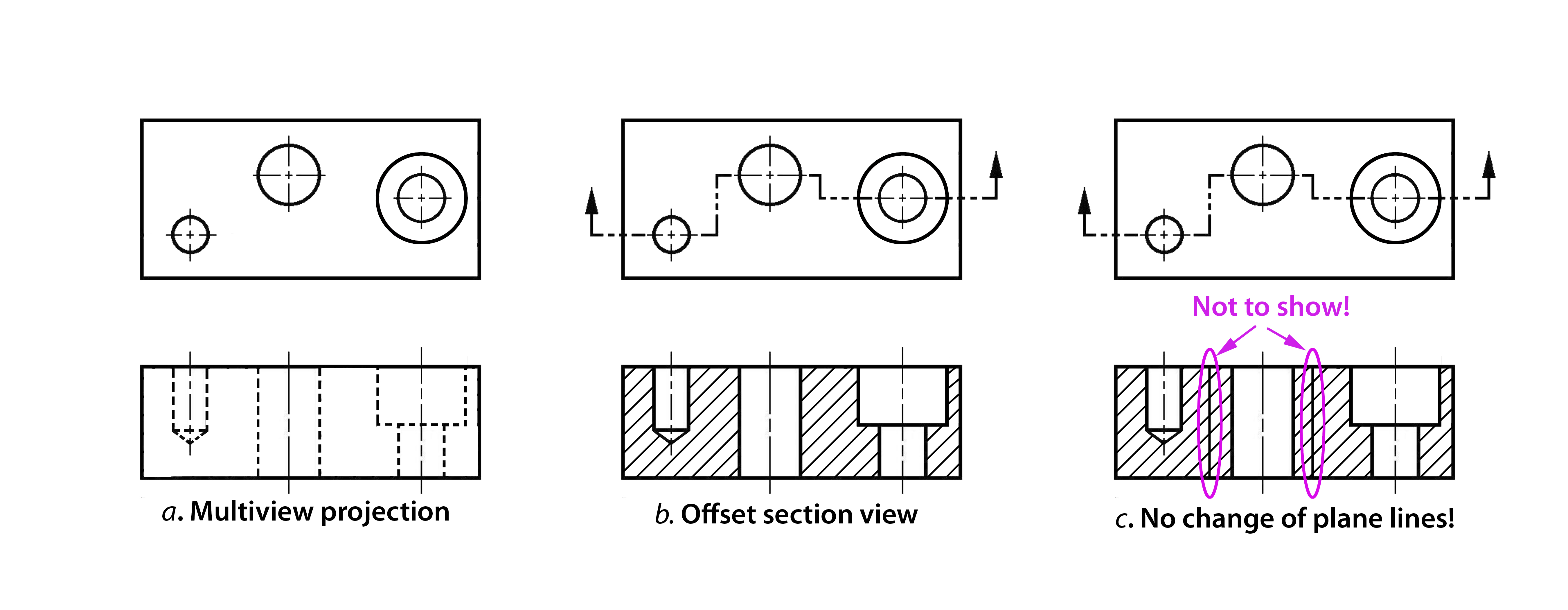
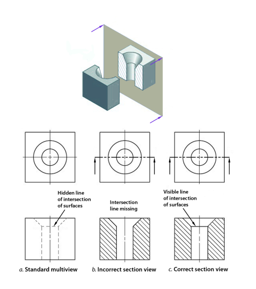
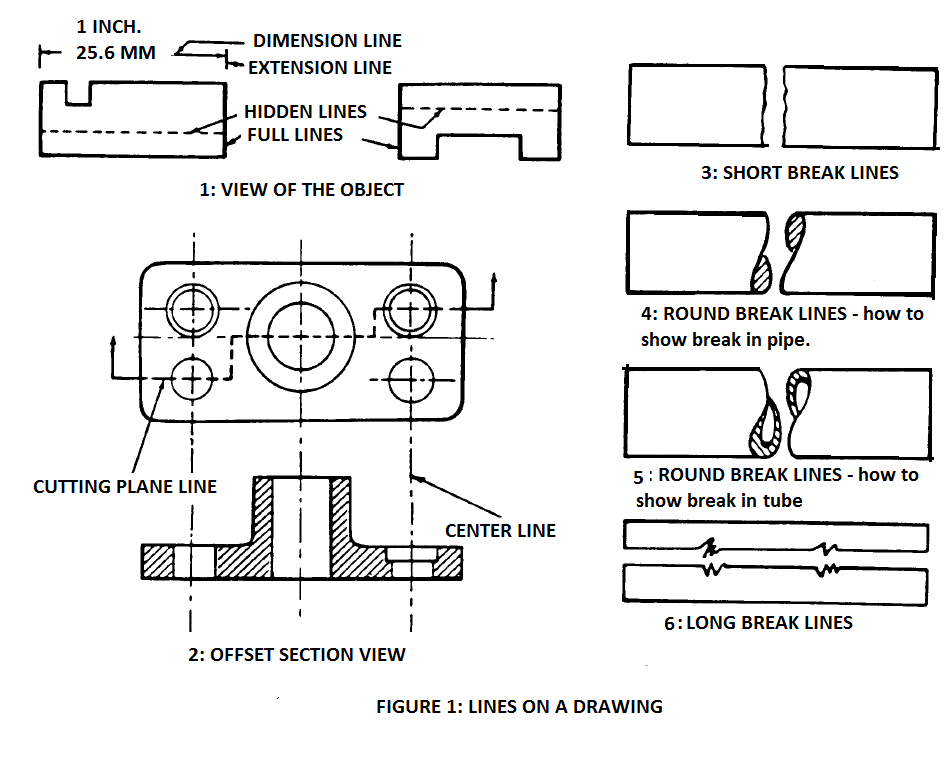
A Section Line On A Drawing Shows The North Orientation - Site plan should show the orientation (true and project north) and that's it. The main elements of the section view are: Web (for section line, you can break and offset the line to focus on key interior and/or architectural elements. Section line, section reference arrow,. Web with all respect, adding north arrow in floor plans is not helping anyone in any way. Web cutting plane lines are thick (.7mm) dashed lines, that extend past the edge of the object 1/4 or 6mm and have line segments at each end drawn at 90 degrees and terminated. Web the picture below shows how our object would be represented in the engineering drawing. Shows an object as if part of it were cut away to expose its insides. The line should start and stop outside of the plan, and you should. Web a section drawing is one that shows a vertical cut transecting, typically along a primary axis, an object or building. Section line, section reference arrow,. The line should start and stop outside of the plan, and you should. The section view shows the sectioned. The arrows indicate the viewing direction. Web in short, a section drawing is a view that depicts a vertical plane cut through a portion of the project. Web section lines are bidirectional and you can specify the length and depth of the section line either visually, using the pointing device, or by entering numeric values. A section line on a drawing shows the location of the section on the plan, not the north orientation. Web a section drawing is one that shows a vertical cut transecting, typically. The main elements of the section view are: The arrows on cutting plane lines show the _____________ of the sectional. Web a dashed or “phantom” cutting line on the parent view indicates the location of the cutting plane. Web section lines are bidirectional and you can specify the length and depth of the section line either visually, using the pointing. Web section lines are bidirectional and you can specify the length and depth of the section line either visually, using the pointing device, or by entering numeric values. Web section lining is a method of representing internal features of an object in an engineering drawing. Web a section drawing is one that shows a vertical cut transecting, typically along a. Web with all respect, adding north arrow in floor plans is not helping anyone in any way. The section reveals simultaneously its interior and exterior. Web section lines are bidirectional and you can specify the length and depth of the section line either visually, using the pointing device, or by entering numeric values. Hello in my autocad project the north. Web in short, a section drawing is a view that depicts a vertical plane cut through a portion of the project. The line should start and stop outside of the plan, and you should. Web a section line on a drawing that shows the north orientation is often referred to as the north arrow. Web a dashed or “phantom” cutting. Web with all respect, adding north arrow in floor plans is not helping anyone in any way. The arrows on cutting plane lines show the _____________ of the sectional. Web a section drawing is one that shows a vertical cut transecting, typically along a primary axis, an object or building. The section reveals simultaneously its interior and exterior. Web a. The sections would most likely be two or more sections cut at 90 degrees of one another to give. Web the picture below shows how our object would be represented in the engineering drawing. Web with all respect, adding north arrow in floor plans is not helping anyone in any way. Web a set of flashcards for level 1 module. Shows an object as if part of it were cut away to expose its insides. These views are usually represented via annotated section lines. Web a dashed or “phantom” cutting line on the parent view indicates the location of the cutting plane. In geographical terms, the north direction is relating to the. Web a set of flashcards for level 1. The main elements of the section view are: These views are usually represented via annotated section lines. Learn terms such as section line, branch circuit, dimension, scale, and more. The section view shows the sectioned. A section line on a drawing shows the location of the section on the plan, not the north orientation. Web message 1 of 4. A section line on a drawing shows the location of the section on the plan, not the north orientation. The arrows indicate the viewing direction. Web section lining is a method of representing internal features of an object in an engineering drawing. Web a set of flashcards for level 1 module 10 of electrical construction drawings. Web cutting plane lines are thick (.7mm) dashed lines, that extend past the edge of the object 1/4 or 6mm and have line segments at each end drawn at 90 degrees and terminated. The line should start and stop outside of the plan, and you should. The sections would most likely be two or more sections cut at 90 degrees of one another to give. Web the picture below shows how our object would be represented in the engineering drawing. Web in short, a section drawing is a view that depicts a vertical plane cut through a portion of the project. Shows an object as if part of it were cut away to expose its insides. Web a section drawing is one that shows a vertical cut transecting, typically along a primary axis, an object or building. Web section lines on a drawing indicate a surface that has been cut or sliced in a section view. Web (for section line, you can break and offset the line to focus on key interior and/or architectural elements. These views are usually represented via annotated section lines. Web a dashed or “phantom” cutting line on the parent view indicates the location of the cutting plane.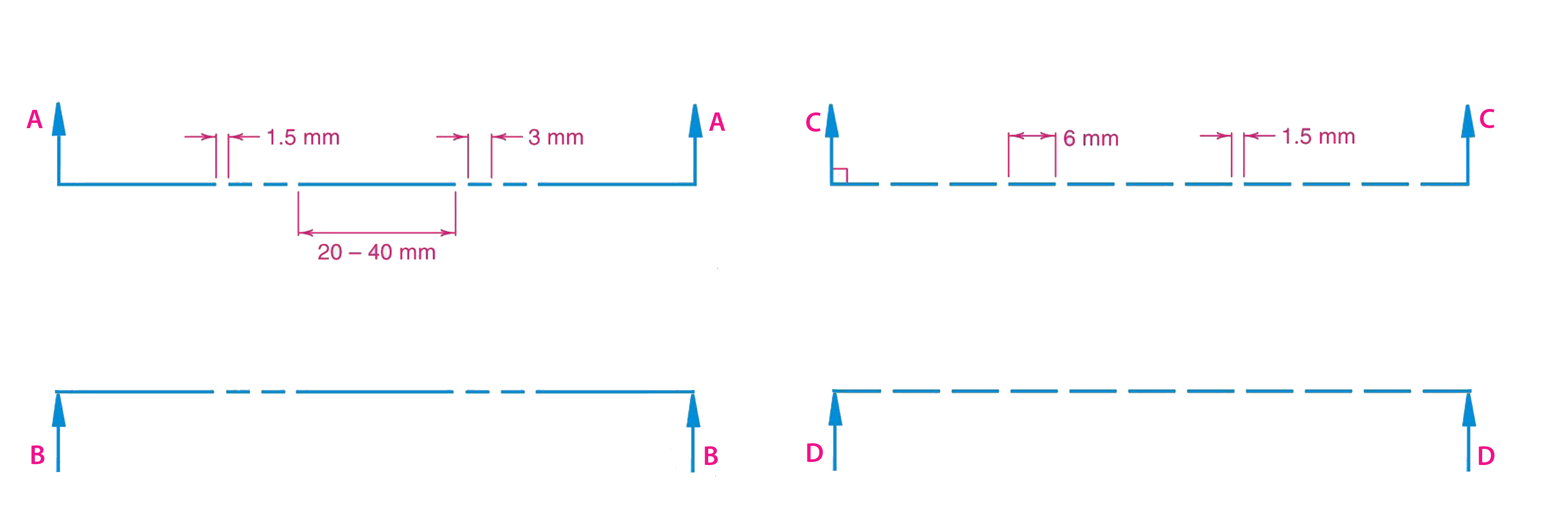
Hidden Line in Engineering Drawing Curl Gredyet
What Is A Sectional View Types Of Sectional Views My XXX Hot Girl
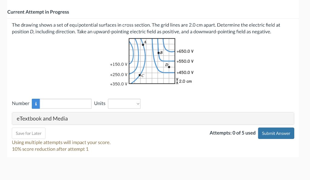
Solved The drawing shows a set of equipotential surfaces in

Proko Practice Section Lines

Solidworks Section View Drawing What's New in SOLIDWORKS 2017
Sectioning Technique Engineering Design McGill University

Luftwaffe Messerschmitt Me163 Komet Section LineDrawing Technical
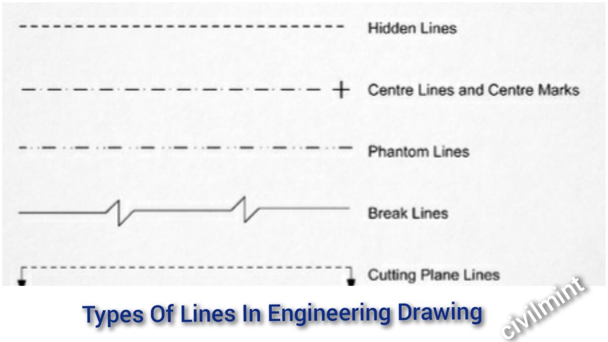
Types Of Lines In Engineering Drawing

what is annotated drawing
Weld Symbols Lines On A Drawing
Site Plan Should Show The Orientation (True And Project North) And That's It.
Web Learn Electrical Drawing Terms And Symbols With This Set Of 40 Flashcards.
Hello In My Autocad Project The North Is Not.
In Geographical Terms, The North Direction Is Relating To The.
Related Post: