Drawing Chamfer Callout
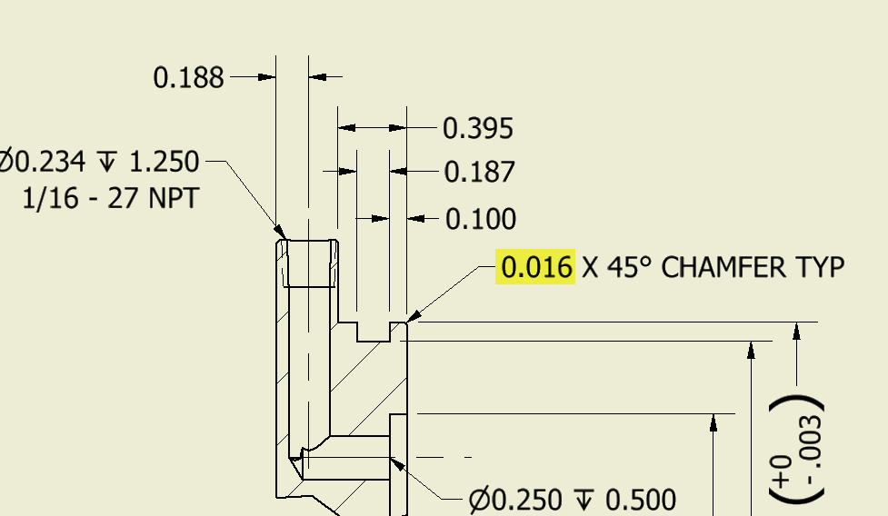
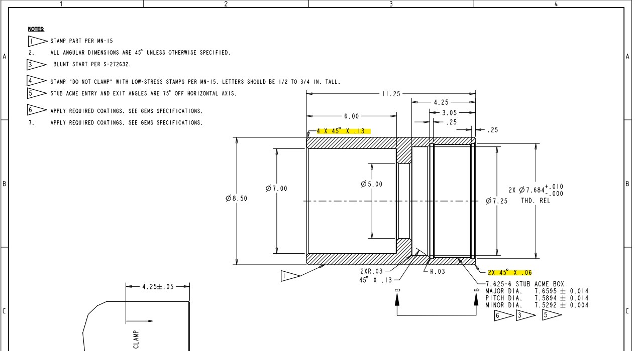
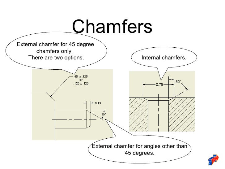
Drawing Chamfer Callout - I have been using this style for many years with multiple companies and drafting programs and have never questioned it. • standard language is english (uk). If an angle other than 45 degrees is dimensioned, the surface to which the angle is measured must be made clear on the drawing. This is good only for sketches and preliminary design drawings. X display is the size of the x in a chamfer dimension with two numbers, such as 1 x 45° (length x angle), 45° x 1 (angle x length), 1 x 1 (length x length) or. General notes apply to the entire drawing. I have a cylindrical part with a chamfer at each end. The top of the dashboard lists the different chamfer sets we create. Click chamfer dimension on the dimensions/relations toolbar or click tools > dimensions > chamfer. Mikeatmagnum (mechanical) (op) 19 jul 06 11:03. Select a circle that is part of a hole feature, or a thread that is part of an external thread feature. You must select the chamfered edge first. Drag to place the callout. X display is the size of the x in a chamfer dimension with two numbers, such as 1 x 45° (length x angle), 45° x 1 (angle. Through this method, y14.5 aims to improve quality, lower costs, and shorten deliveries wherever mechanical parts are designed or manufactured. Web steps copy link. Web what is the standard for a callout of a chamfer feature? Asme (ansi) y14.5m is the standard for. Select a circle that is part of a hole feature, or a thread that is part of. Web by crystal bemis on november 10, 2022. X display is the size of the x in a chamfer dimension with two numbers, such as 1 x 45° (length x angle), 45° x 1 (angle x length), 1 x 1 (length x length) or. A comma is used instead of the decimal point. Click chamfer dimension on the dimensions/relations toolbar. Local notes, also referred to as. X display is the size of the x in a chamfer dimension with two numbers, such as 1 x 45° (length x angle), 45° x 1 (angle x length), 1 x 1 (length x length) or. Web regardless of feature size simply means that whatever gd&t callout you make, is controlled independently of the. You must select the chamfered edge first. Erase created dimensions, if needed. Is this correct or do i have it backwards? Web to insert chamfer dimensions into a drawing: Web you can create the dimension wanted in a couple of steps. Web break edge callouts are specified directly on the drawing to reference a certain surface or as a note e.g. This guide will help you to understand what is a chamfer and point out some differences. Web by crystal bemis on november 10, 2022. What is the correct way to call out a 45 degree chamfer? Web to demonstrate an. Web basic dimensioning is the addition of only functional size values to drawing entities. If an angle other than 45 degrees is dimensioned, the surface to which the angle is measured must be made clear on the drawing. Web you can dimension chamfers in drawings. In addition to the usual dimension display properties, chamfer dimensions have their own options for. Is it to call out the note with a leader (.25 x 45°) or to add two seperate dimensions (one linear and chamfer callout? In this article, you will learn the proper way to do a chamfer callout, as well as how to do the callout in popular software programs. • “indications according to iso 10110” appears on the drawing.. Working drawings need tolerances in addition to functional size values. A comma is used instead of the decimal point. Drag to place the callout. This guide will help you to understand what is a chamfer and point out some differences. They are used for a variety of reasons, which typically include: See paragraphs 4.22 and 4.23. Mikeatmagnum (mechanical) (op) 19 jul 06 11:03. Asme does not “approve,” “rate,” or “endorse” any item, construction, proprietary device, or activity. Web you can dimension chamfers in drawings. Erase created dimensions, if needed. Chamfers can be dimensioned in two ways, either by calling out the length by angle, or calling out the length by length. Web what is the standard for a callout of a chamfer feature? Xgrigorix (specifier/regulator) (op) 26 sep 05 14:51. .040 x 30) to my knowledge the.040 be the depth into the material and the 30 degrees is the angle from the centerline. See figure 2 for chamfer dimensioning examples. To access the edge chamfer functionality, click on the following icon in the feature toolbar. If an angle other than 45 degrees is dimensioned, the surface to which the angle is measured must be made clear on the drawing. If the selection was part of a hole feature, the precision, tolerance, fit class tolerance, and shaft class tolerance values from that feature are. I have a cylindrical part with a chamfer at each end. This guide will help you to understand what is a chamfer and point out some differences. Erase created dimensions, if needed. Web steps copy link. A comma is used instead of the decimal point. Web the standard is intended to provide uniformity in drawing specifications and interpretation, reducing guesswork throughout the manufacturing process. Mikeatmagnum (mechanical) (op) 19 jul 06 11:03. Web 16 nov 12 16:15.
Steps to add chamfer dimension in 2D drawing SEACAD
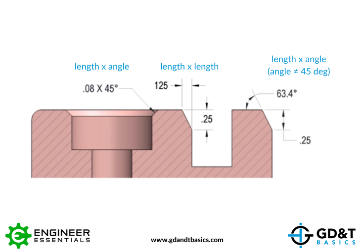
Chamfer Dimensioning GD&T Basics

How to Use SolidWorks Sketch Chamfer Tool Tutorial for Beginners
Inventor Ability to change the decimal places in the call out of the

SolidWorks Tutorial How to Add Chamfer Dimension In Solidworks Drawing
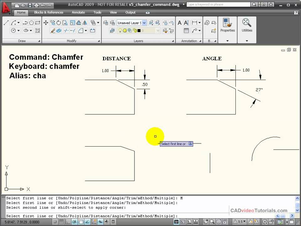
AutoCAD Tutorial Using the CHAMFER Command YouTube
Solved Multiple chamfers on drawings PTC Community
Dimensioning standards

Adding a Chamfer Dimension YouTube

Introduction to AutoCAD Chamfer YouTube
You Must Select The Chamfered Edge First.
Web You Can Create The Dimension Wanted In A Couple Of Steps.
When We Enter Into The Edge Chamfer Tool, We See The Following Dashboard (With The Sets Panel Opened Up).
Web A Chamfer Is A Slope At The Edge Of A Part And A Chamfer Callout Refers To How To Dimension Chamfers On Drawings.
Related Post: