Drawing Symbol
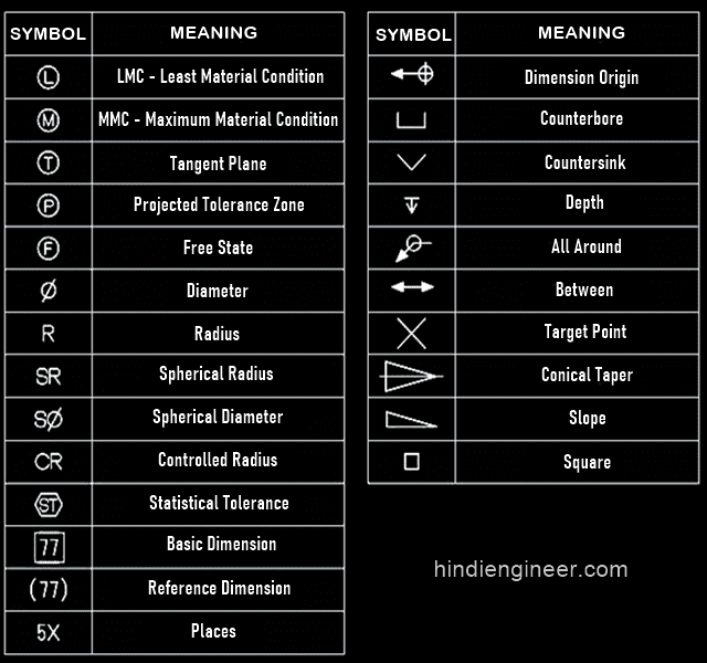
Drawing Symbol - Here are more commonly used engineering drawing symbols and design elements as below. Web a convenient guide for geometric dimensioning and tolerancing (gd&t) symbols at your fingertips. Web — 11 min read. However, symbols can be meaningful only if they are created according to the relevant standards or conventions. They represent components, elements, details, characteristics, actions, features, and conditions important for a defined technical product or system. That’s why we’ve broken down the process into bite size chunks. Many of the definitions are not official asme, ansi or iso terminology. Web engineering drawing abbreviations and symbols are used to communicate and detail the characteristics of an engineering drawing. Most symbols have been in y14.5 since at least 1994. Web may 5, 2022 by brandon fowler. Web engineering drawing symbols are simple to pick up and use once you understand how to read them. Lines that indicate the direction of flow, along with specifications about the pipe size, material, and number. Unlike a model, engineering drawings offer more specific detail and requirements, such as: Web gd&t drawings and symbols. Last updated apr 24, 2024. Most symbols have been in y14.5 since at least 1994. Web basic types of symbols used in engineering drawings are countersink, counterbore, spotface, depth, radius, and diameter. Unlike a model, engineering drawings note much more specific information and requirements, such as: Here are more commonly used engineering drawing symbols and design elements as below. This document describes and illustrates common. Lines that indicate the direction of flow, along with specifications about the pipe size, material, and number. Web — 11 min read. In this chapter we will study what constitutes good drafting technique for each line type. Web may 1, 2022 by brandon fowler. Geometric tolerances are specified using symbols on a drawing. In construction, every blueprint and drawing is a complex web of information, distilled into symbols and lines that determine the work executed onsite. Below, you’ll find our list of drafting symbols in alphabetical order. Web various symbols and abbreviations in engineering drawings give you information about the dimensions, design, and materials used. Symbols provide a “common language” for drafters all. Web may 5, 2022 by brandon fowler. Learning to read blueprints can be hard. Geometric tolerances are specified using symbols on a drawing. Click on the links below to learn more about each gd&t symbol or concept, and be sure to download the free wall chart for a quick reference when at. Web 5 types of gd&t symbols. Web the table shows dimensioning symbols found on drawings. These symbols and abbreviations are standardized by the american national standards institute (asmi) and the american society of mechanical engineers (asme) in the us. They represent components, elements, details, characteristics, actions, features, and conditions important for a defined technical product or system. Click on the links below to learn more about. You can also check out the gd&t symbols and terms on our site. Lines that indicate the direction of flow, along with specifications about the pipe size, material, and number. Geometric tolerances are specified using symbols on a drawing. However, symbols can be meaningful only if they are created according to the relevant standards or conventions. All of the basic. In the design industry, there are standardized line types and correct techniques to be used for producing professionally hand drafted drawings. They are 1) piping and instrument drawings (p&ids), 2) electrical single lines and schematics, 3) electronic diagrams and schematics, 4) logic diagrams and prints, and 5) fabrication, construction, and architectural drawings. Symbols provide a “common language” for drafters all. Web how to read an engineering drawing symbol. Learning to read blueprints can be hard. Symbols provide a “common language” for drafters all over the world. Here are more commonly used engineering drawing symbols and design elements as below. Many of the definitions are not official asme, ansi or iso terminology. This list includes abbreviations common to the vocabulary of people who work with engineering drawings in the manufacture and inspection of parts and assemblies. In this chapter we will study what constitutes good drafting technique for each line type. An introduction to the different types of blueprint tolerances you will encounter with plenty of examples to make them easy to. This list includes abbreviations common to the vocabulary of people who work with engineering drawings in the manufacture and inspection of parts and assemblies. Web symbols in mechanical drawings are graphical elements accepted by standards and codes. Web the table shows dimensioning symbols found on drawings. Unlike a model, engineering drawings note much more specific information and requirements, such as: Web — 11 min read. In construction, every blueprint and drawing is a complex web of information, distilled into symbols and lines that determine the work executed onsite. Lines that indicate the direction of flow, along with specifications about the pipe size, material, and number. This document describes and illustrates common dimensioning, gd&t, architectural, piping, and electrical symbols. Here are more commonly used engineering drawing symbols and design elements as below. Web engineering drawing symbols are simple to pick up and use once you understand how to read them. These symbols and abbreviations are standardized by the american national standards institute (asmi) and the american society of mechanical engineers (asme) in the us. Web a convenient guide for geometric dimensioning and tolerancing (gd&t) symbols at your fingertips. Web 5 types of gd&t symbols. Web this chapter will introduce the five common categories of drawings. Below, you’ll find our list of drafting symbols in alphabetical order. Geometric tolerances are specified using symbols on a drawing.
How To Read Architectural Drawings Symbols The Architect

Mechanical Engineering Drawing Symbols Pdf Free Download at
M&e Drawing Symbols Back To Basics Komseq
Engineering Drawing Symbols List Chart Explain Mechanical Drawing

Civil Engineering Drawing Symbols And Their Meanings at PaintingValley

Engineering Drawing Symbols And Their Meanings Pdf at PaintingValley

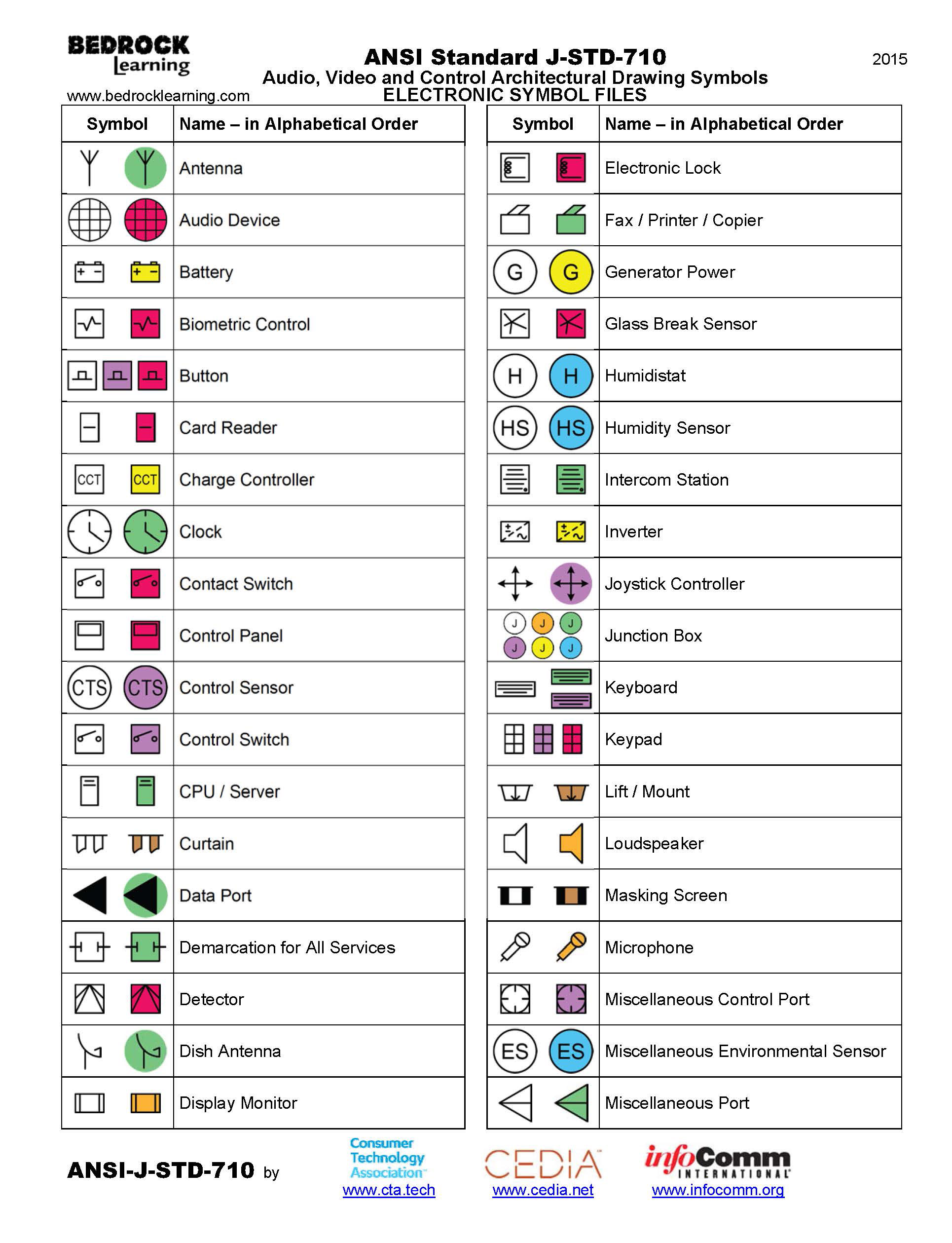
ANSI Standard JSTD710 Architectural Drawing Symbols Bedrock Learning
Architectural Drawing Symbols Free Download at GetDrawings Free download

Standard Engineering Drawing Symbols
Civil Engineering Drawing Symbols And Their Meanings at PaintingValley
Web May 1, 2022 By Brandon Fowler.
Note The Comparison With The Iso Standards.
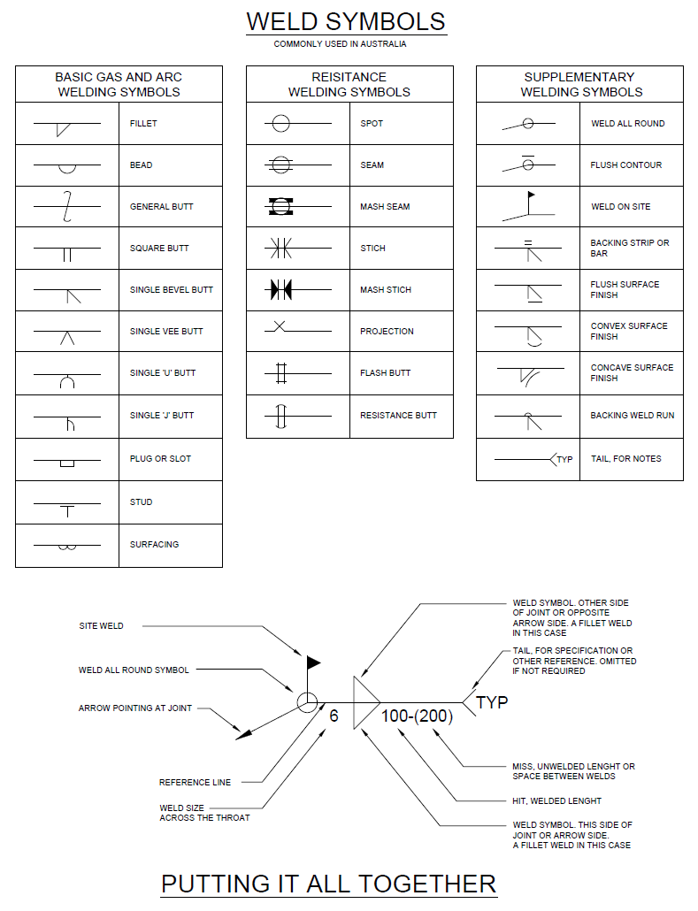
Web Some Common Engineering Drawing Symbols Include Geometric Symbols (Circle, Square, Triangle), Symbols For Surface Finish (Roughness, Smoothness), Symbols For Welding (Fillet Weld, Plug Weld), Symbols For Electrical Circuits (Resistor, Capacitor), And Symbols For Mechanical Components (Gears, Bearings).
Web Engineering Drawing Abbreviations And Symbols Are Used To Communicate And Detail The Characteristics Of An Engineering Drawing.
Related Post:
