Engineering Drawing Symbols And Meanings
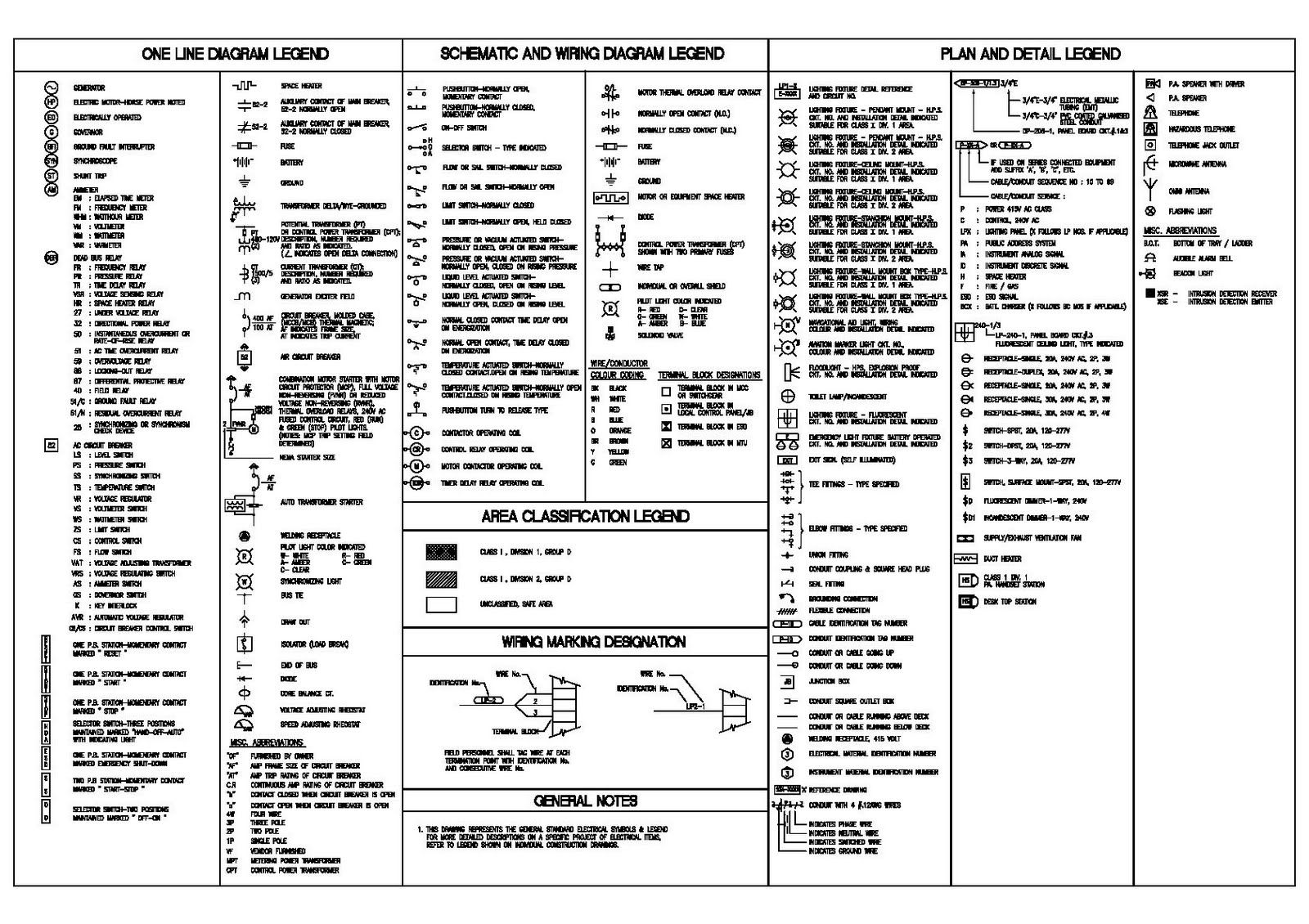
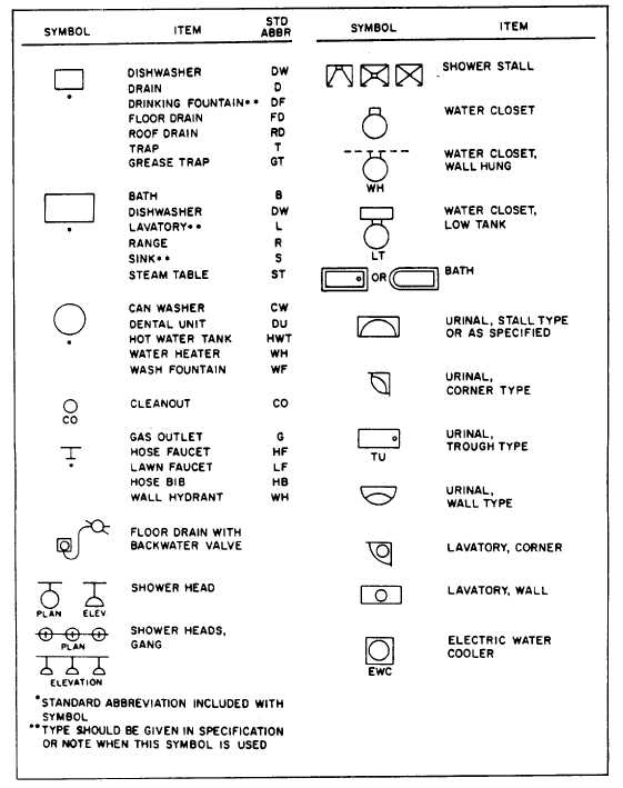
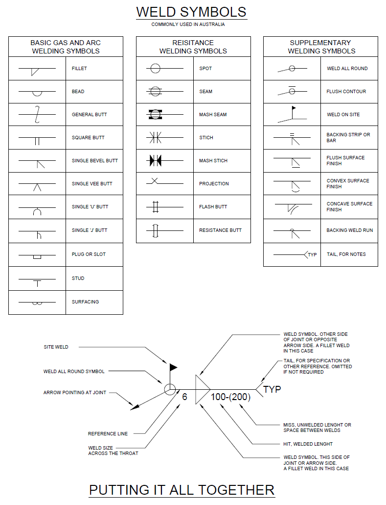
Engineering Drawing Symbols And Meanings - This makes understanding the drawings simple with little to no personal interpretation possibilities. This document describes and illustrates common dimensioning, gd&t, architectural, piping, and electrical symbols. Web engineering drawing abbreviations and symbols are used to communicate and detail the characteristics of an engineering drawing. For example, cold rolled steel is often abbreviated as crs, and diameter is often abbreviated as dia, d, or ⌀. All of the basic components of an engineering drawing are detailed below with links throughout to. “learning gd&t from scratch,” provided by keyence, walks you through the basics of geometric dimensioning and tolerancing, datums, and measurements by coordinate measuring. They are 1) piping and instrument drawings (p&ids), 2) electrical single lines and schematics, 3) electronic diagrams and schematics, 4) logic diagrams and prints, and 5) fabrication, construction, and architectural drawings. Web engineering drawings (aka blueprints, prints, drawings, mechanical drawings) are a rich and specific outline that shows all the information and requirements needed to manufacture an item or product. However, symbols can be meaningful only if they are created according to the relevant standards or conventions. Engineering drawing symbols play a vital role in communication among engineers and other stakeholders involved in the design and construction process. Unlike a model, engineering drawings offer more specific detail and requirements, such as: However, symbols can be meaningful only if they are created according to the relevant standards or conventions. Web what are the most commonly used engineering drawing symbols and their meanings? An engineering drawing often tells the specific requirements and detail, such as: All of the basic components. So let’s look at the different line and view types you will come across in the engineering discipline. Engineering drawing symbols play a vital role in communication among engineers and other stakeholders involved in the design and construction process. Almost any geometric form can easily be controlled with geometric dimensioning and tolerancing. A series of standard symbols indicates each variation.. All of the basic components of an engineering drawing are detailed below with links throughout to. The true position theory and the specification of tolerance zones are also explained. This list includes abbreviations common to the vocabulary of people who work with engineering drawings in the manufacture and inspection of parts and assemblies. Web what are the most commonly used. Web gd&t symbols charts for engineering drawing & drafting | geotol. Unlike a model, engineering drawings offer more specific detail and requirements, such as: Web engineering drawings (aka blueprints, prints, drawings, mechanical drawings) are a rich and specific outline that shows all the information and requirements needed to manufacture an item or product. Web eo 1.8 identify the symbols used. Web what are the most commonly used engineering drawing symbols and their meanings? For example, cold rolled steel is often abbreviated as crs, and diameter is often abbreviated as dia, d, or ⌀. Web once you understand the meaning and definition of the symbols and abbreviations, you’ll pick up and use the engineering drawing with ease. To limit errors caused. The table shows dimensioning symbols found on drawings. That’s why we’ve broken down the process into bite size chunks. Web the following is a short list of symbols that normally appear on a technical drawing and need understanding. They are 1) piping and instrument drawings (p&ids), 2) electrical single lines and schematics, 3) electronic diagrams and schematics, 4) logic diagrams. “learning gd&t from scratch,” provided by keyence, walks you through the basics of geometric dimensioning and tolerancing, datums, and measurements by coordinate measuring. Web gd&t symbols charts for engineering drawing & drafting | geotol. All of the basic components of an engineering drawing are detailed below with links throughout to. Compressors symbology to read and interpret piping and instrument drawings. Why not just use a 3d model? You can also check out the gd&t symbols and terms on our site. This document describes and illustrates common dimensioning, gd&t, architectural, piping, and electrical symbols. “learning gd&t from scratch,” provided by keyence, walks you through the basics of geometric dimensioning and tolerancing, datums, and measurements by coordinate measuring. Learn the ins and. For example, cold rolled steel is often abbreviated as crs, and diameter is often abbreviated as dia, d, or ⌀. Web the following is a short list of symbols that normally appear on a technical drawing and need understanding. An engineering drawing often tells the specific requirements and detail, such as: So let’s look at the different line and view. Web once you understand the meaning and definition of the symbols and abbreviations, you’ll pick up and use the engineering drawing with ease. “learning gd&t from scratch,” provided by keyence, walks you through the basics of geometric dimensioning and tolerancing, datums, and measurements by coordinate measuring. Web a convenient guide for geometric dimensioning and tolerancing (gd&t) symbols at your fingertips.. Web engineering drawings (aka blueprints, prints, drawings, mechanical drawings) are a rich and specific outline that shows all the information and requirements needed to manufacture an item or product. That’s why we’ve broken down the process into bite size chunks. Web basic types of symbols used in engineering drawings are countersink, counterbore, spotface, depth, radius, and diameter. This list includes abbreviations common to the vocabulary of people who work with engineering drawings in the manufacture and inspection of parts and assemblies. Web once you understand the meaning and definition of the symbols and abbreviations, you’ll pick up and use the engineering drawing with ease. This list includes abbreviations common to the vocabulary of people who work with engineering drawings in the manufacture and inspection of parts and assemblies. An introduction to the different types of blueprint tolerances you will encounter with plenty of examples to make them easy to understand. Web this page explains the 16 symbols used in gd&t, and the classification thereof. We offer you our tips which we believe are useful for dispelling uncertainty by comparing the symbol with its graphic representation. Web eo 1.8 identify the symbols used on engineering p&ids for the following types of system components: This makes understanding the drawings simple with little to no personal interpretation possibilities. To limit errors caused by personal interpretation, engineering drawings and diagrams are governed by standardized language and symbols. Radius can be for the inside and outside curved surface on the part. Web gd&t symbols charts for engineering drawing & drafting | geotol. The table shows dimensioning symbols found on drawings. Here are more commonly used engineering drawing symbols and design elements as below.
Engineering Drawing Symbols And Their Meanings Pdf at PaintingValley

Engineering Drawing Symbols And Their Meanings Pdf at PaintingValley
Engineering Drawing Symbols And Their Meanings Pdf at PaintingValley

Civil Engineering Drawing Symbols And Their Meanings at PaintingValley

Mechanical Engineering Drawing Symbols Pdf Free Download at

Standard Engineering Drawing Symbols Design Talk

ANSI Standard JSTD710 Architectural Drawing Symbols Bedrock Learning

Engineering Drawing Symbols And Their Meanings Pdf at PaintingValley
Civil Engineering Drawing Symbols And Their Meanings at PaintingValley
Engineering Drawing Symbols And Their Meanings Pdf at PaintingValley
Note The Comparison With The Iso Standards.
Unlike A Model, Engineering Drawings Offer More Specific Detail And Requirements, Such As:
Web The Following Is A Short List Of Symbols That Normally Appear On A Technical Drawing And Need Understanding.
This Document Describes And Illustrates Common Dimensioning, Gd&T, Architectural, Piping, And Electrical Symbols.
Related Post: