Gdt Drawing Examples
Gdt Drawing Examples - Gdt overview nominal dimensions, basic dimensions, reference dimensions chain dimensions, baseline dimensions, direct dimensions, ordinate dimensions, gtol symbols learning gd&t. Gd&t symbols and definitions help convey the designed object and allow for the manufacturing of mechanical parts in a way that improves quality, lowers manufacturing costs, and shortens delivery time. Web may 1, 2022 by brandon fowler. Web this guide walks through the gd&t system for streamlining communication about the design in both traditional and digital manufacturing. The first tool in your engineering drawing toolbox is the drawing view. Web provides a concise way to describe a reference coordinate system (datums) of a component or assembly to be used throughout the manufacturing and inspection processes. Gd&t positions every part within a datum reference frame (drf). Click on the links below to learn more about each gd&t symbol or concept, and be sure to download the free wall chart for a quick reference when at. Currently, we have 16 symbols for geometric tolerances, which are categorised according to the tolerance they specify. These are grouped into symbols relating to form, profile, orientation, runout and location. Parallelism is a fairly common symbol that describes a parallel orientation of one referenced feature to a datum surface or line. Web there are 7 aspects of the gd&t methodology that we will discuss, these include: Read on to learn about: We can create a local coordinate system just for the four holes. Geometric dimensioning and tolerancing, by d. True position, or just position as the asme y14.5 standard calls it, is defined as the total permissible variation that a feature can have from its “true” position. The first tool in your engineering drawing toolbox is the drawing view. However it was not used to any degree until world war ii (ww ii) because until then the. Gd&t controls. Gdt overview nominal dimensions, basic dimensions, reference dimensions chain dimensions, baseline dimensions, direct dimensions, ordinate dimensions, gtol symbols learning gd&t. Some say the drf is the most important concept in geometric positioning and tolerancing because it provides the skeleton or frame of reference to which all requirements are connected. Reduces the amount of notes, dimensions, and tolerances on a drawing;. Gd&t controls variations of size, form, orientation, location and runout individually or in combination. This course will teach you the basics of how to understand gd&t symbols and their use. The goal of gd&t is to hold this variation within set limits. Web may 1, 2022 by brandon fowler. In this drawing, there are four screw holes near the center. It comes in useful if a feature is to be defined on a drawing that needs to be uniformly flat without tightening any other dimensions on the drawing. It is more correctly referred to as “position”. Web gd&t flatness is very straight forward. Views, dimensions, tolerances, symbols, datum’s, feature control frames & title blocks. Gd&t symbols and definitions help convey. Web the concept of geometric dimensioning and tolerancing (gd&t) was introduced by stanley parker from scotland in the late 1930’s. Review the slides use your reference material to find the errors. Read on to learn about: It is a common symbol that references how flat a surface is regardless of any other datums or features. However it was not used. Some say the drf is the most important concept in geometric positioning and tolerancing because it provides the skeleton or frame of reference to which all requirements are connected. Web true position (gd&t) we know that manufactured products can never match their theoretical drawings perfectly. The goal of gd&t is to hold this variation within set limits. Web gd&t is. It is more correctly referred to as “position”. Web this page explains the 16 symbols used in gd&t, and the classification thereof. The actual size varies from the intended design. Web guesswork is never recommended in engineered products. True position theory (size value in rectangular frame) Web gd&t flatness is very straight forward. It is more correctly referred to as “position”. In this drawing, there are four screw holes near the center of the part that don’t interface with any of the other features. Let’s take a look at an example of when to use a local coordinate system: Web gd & t is the vocabulary. Web guesswork is never recommended in engineered products. Web asme y14.5 is an established, widely used gd&t standard containing all the necessary information for a comprehensive gd&t system. It is more correctly referred to as “position”. Web this guide walks through the gd&t system for streamlining communication about the design in both traditional and digital manufacturing. Web gd & t. The following slides contain some errors. Web gd & t is the vocabulary of engineering drawing. Web this guide walks through the gd&t system for streamlining communication about the design in both traditional and digital manufacturing. Web gd&t flatness is very straight forward. With features like maximum material condi. In this drawing, there are four screw holes near the center of the part that don’t interface with any of the other features. Gd&t symbols and definitions help convey the designed object and allow for the manufacturing of mechanical parts in a way that improves quality, lowers manufacturing costs, and shortens delivery time. The “ true position” is the exact coordinate, or location defined by basic dimensions or other means that represents the nominal value. True position, or just position as the asme y14.5 standard calls it, is defined as the total permissible variation that a feature can have from its “true” position. Web this page explains the 16 symbols used in gd&t, and the classification thereof. Engineering drawing and design by d. Read on to learn about: Web may 1, 2022 by brandon fowler. Geometric dimensioning and tolerancing, by d. Web a simple drawing with gd&t datum symbols. Gd&t controls variations of size, form, orientation, location and runout individually or in combination.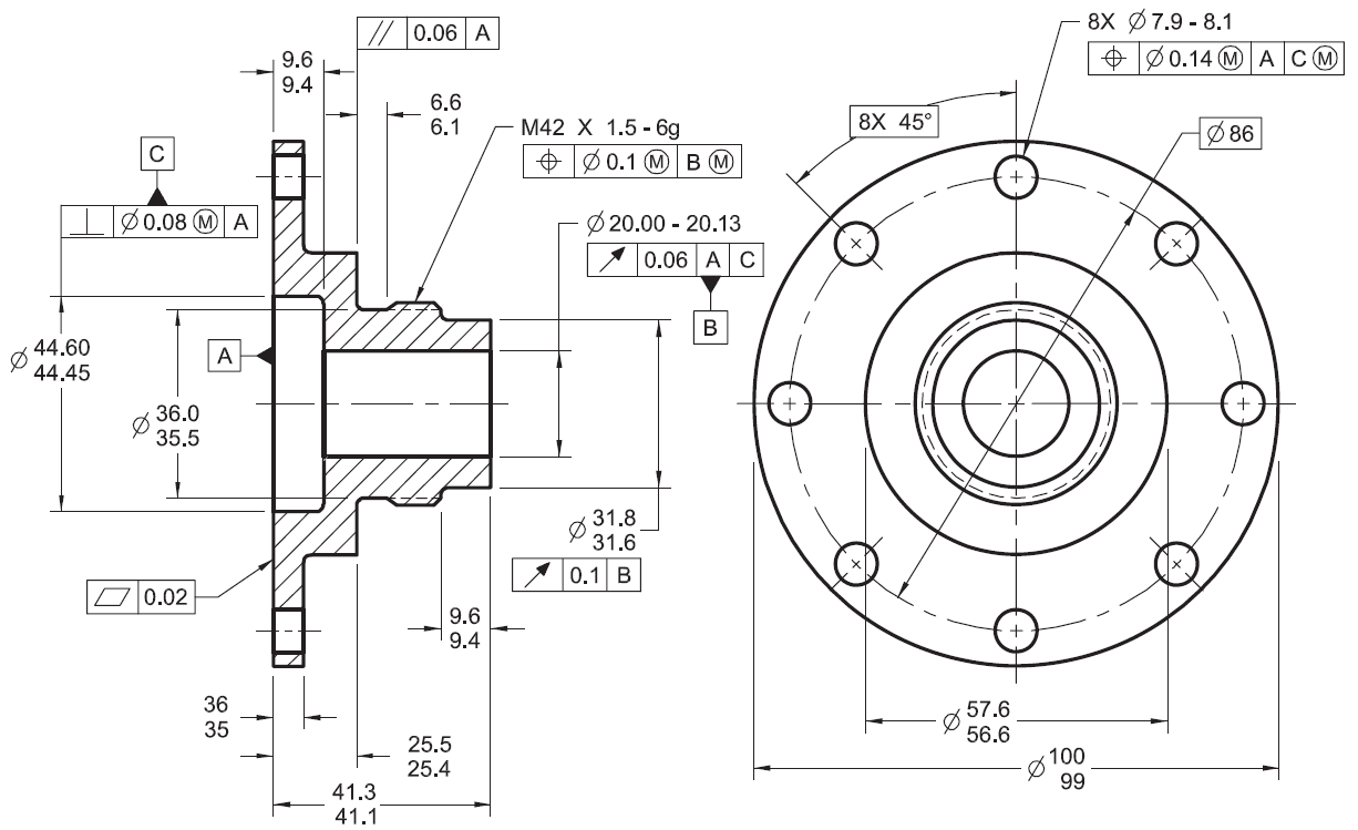
GD&T Drawings KOHLEX
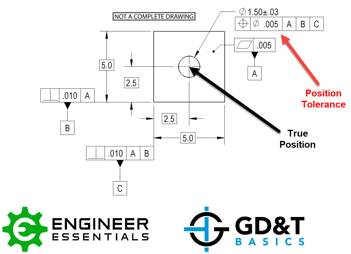
True Position Position Tolerance GD&T Basics

GD&T The Beginner's Guide to Geometric Dimensioning and Tolerancing

GD&T 101 An Introduction to Geometric Dimensioning and Tolerancing

GD&T Tips Profile As a General Tolerance

GD&T Drawings KOHLEX
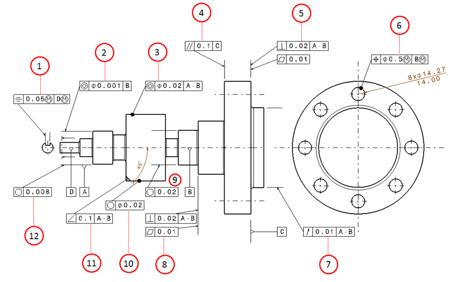
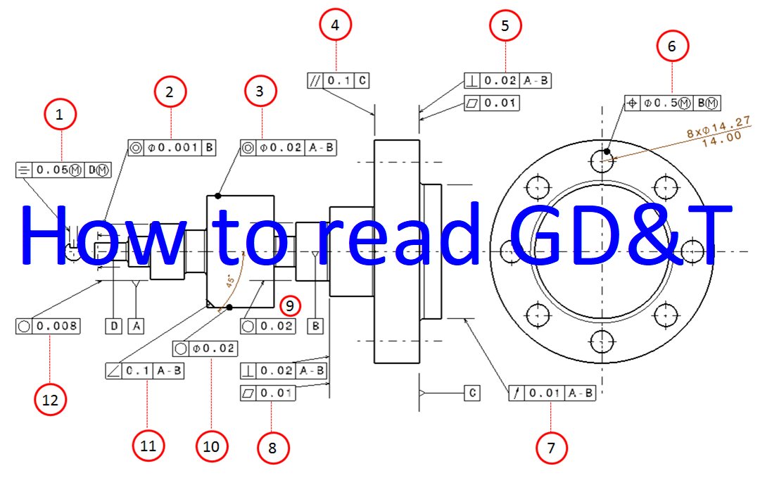
Examples on how to interpret GD&T Form, orientation, location and run
Examples on how to interpret GD&T Form, orientation, location and run

GD&T Basics What You Need to Know

GD&T for beginners step by step approach to do gd&t for mechanical
Web Common Gd&T Symbols Are Listed In The Table Below.
It Is More Correctly Referred To As “Position”.
Web True Position (Gd&T) We Know That Manufactured Products Can Never Match Their Theoretical Drawings Perfectly.
These Are Grouped Into Symbols Relating To Form, Profile, Orientation, Runout And Location.
Related Post: