Isometric Pipe Drawing
Isometric Pipe Drawing - Web an extensive discussion of the need for, and development of, piping isometric drawings is provided. Each serves a unique purpose and offers different perspectives to engineers, designers, and builders, ensuring a comprehensive understanding of the piping system’s layout, design, and functionality. Piping isometric drawing is a representation of 3d view of piping layout of the plant. Piping iso symbols and meaning. An explanation of how piping isometrics are created from plan and elevation views is explained. Setting up the iso drawing. Choose between metric units or us units, and click create. The use of a north arrow in establishing pipe orientation and routing on the isometric is shown graphically. The drawing axes of the isometrics intersect at an angle of 60°. Web an isometric drawing is a type of pictorial drawing in which three sides of an object can be seen in one view. Each serves a unique purpose and offers different perspectives to engineers, designers, and builders, ensuring a comprehensive understanding of the piping system’s layout, design, and functionality. Import idf or pcf files. Web isometrics are usually drawn from information found on a plan and elevation views. Web use basic shapes in isometric drawings. Explore the possibilities of piping design with picad®. Usually, piping isometrics are drawn on preprinted paper, with lines of equilateral triangles form of 60°. Web pipeline isometrics are detailed drawings used in engineering and design to represent the 3d layout of a pipeline system on a 2d surface. Each serves a unique purpose and offers different perspectives to engineers, designers, and builders, ensuring a comprehensive understanding of the. Piping isometric drawings are detailed technical illustrations that show a 3d view of piping systems. Web piping isometric drawing consists of three sections. 3 clicks to draw a pipe, 3 clicks to add an elbow, 1 click to add a dimension and 3 clicks to print. Web isometric, plan, and elevation presentations are three distinct types of drawings used to. Web how to read piping isometrics using real plant drawings. Web © 2024 google llc. The use of a north arrow in establishing pipe orientation and routing on the isometric is shown graphically. An isometric drawing covers a complete line as per the line list and p&id. Web © 2023 google llc. Setting up the iso drawing. Web pipeline isometrics are detailed drawings used in engineering and design to represent the 3d layout of a pipeline system on a 2d surface. Web iso pipes are typically drawn using specialized software such as avicad which supports isometric drawings. Web an extensive discussion of the need for, and development of, piping isometric drawings is. Each serves a unique purpose and offers different perspectives to engineers, designers, and builders, ensuring a comprehensive understanding of the piping system’s layout, design, and functionality. Web drawing piping isometrics : Section of left or right of piping isometric drawing includes: Choose between metric units or us units, and click create. What you will get in this course. Piping isometric drawing is a representation of 3d view of piping layout of the plant. Accurate drawing symbols, callouts, precise coordinates, and elevations provide intricate information to the fabricator. Each serves a unique purpose and offers different perspectives to engineers, designers, and builders, ensuring a comprehensive understanding of the piping system’s layout, design, and functionality. These highly structured drawings provide. Web an extensive discussion of the need for, and development of, piping isometric drawings is provided. Dimensions and location of instruments. What you will get in this course. Web the process of drafting isometric drawings for a pipeline system involves referencing the arrangements of the pipelines, sections, and elevation drawings during its development. Piping joint types, weld types. Web what are pipeline isometric drawings? Piping isometric drawings are detailed technical illustrations that show a 3d view of piping systems. These highly structured drawings provide a comprehensive 3d representation of the arrangement, dimensions, and connections of pipes within a system. 3 clicks to draw a pipe, 3 clicks to add an elbow, 1 click to add a dimension and. Create an isometric drawing with a block diagram with perspective template. Web how to read piping isometrics using real plant drawings. Web isometric drawings are typically used to show the details of a piping system, such as the size and type of piping, the direction of flow of the fluids, and the location of valves, pumps, and other equipment nozzles.. Usually, piping isometrics are drawn on preprinted paper, with lines of equilateral triangles form of 60°. Choose between metric units or us units, and click create. The use of a north arrow in establishing pipe orientation and routing on the isometric is shown graphically. No more tedious material tracking when creating a pipe isometric drawing. In visio, on the file menu, click new, and then click basic drawing. Create an isometric drawing from scratch. The symbols that represent fittings, valves and flanges are modified to adapt to the isometric grid. Web piping isometric drawing consists of three sections. 3 clicks to draw a pipe, 3 clicks to add an elbow, 1 click to add a dimension and 3 clicks to print. Web isometric, plan, and elevation presentations are three distinct types of drawings used to depict piping systems in engineering and construction. Weld joint type and its location; Web what are pipeline isometric drawings? How to read iso drawings. Import idf or pcf files. Line list (process) latest p&id/pefs (process) (issued signed copy) general information about piping isometric drawings. Explore the possibilities of piping design with picad®.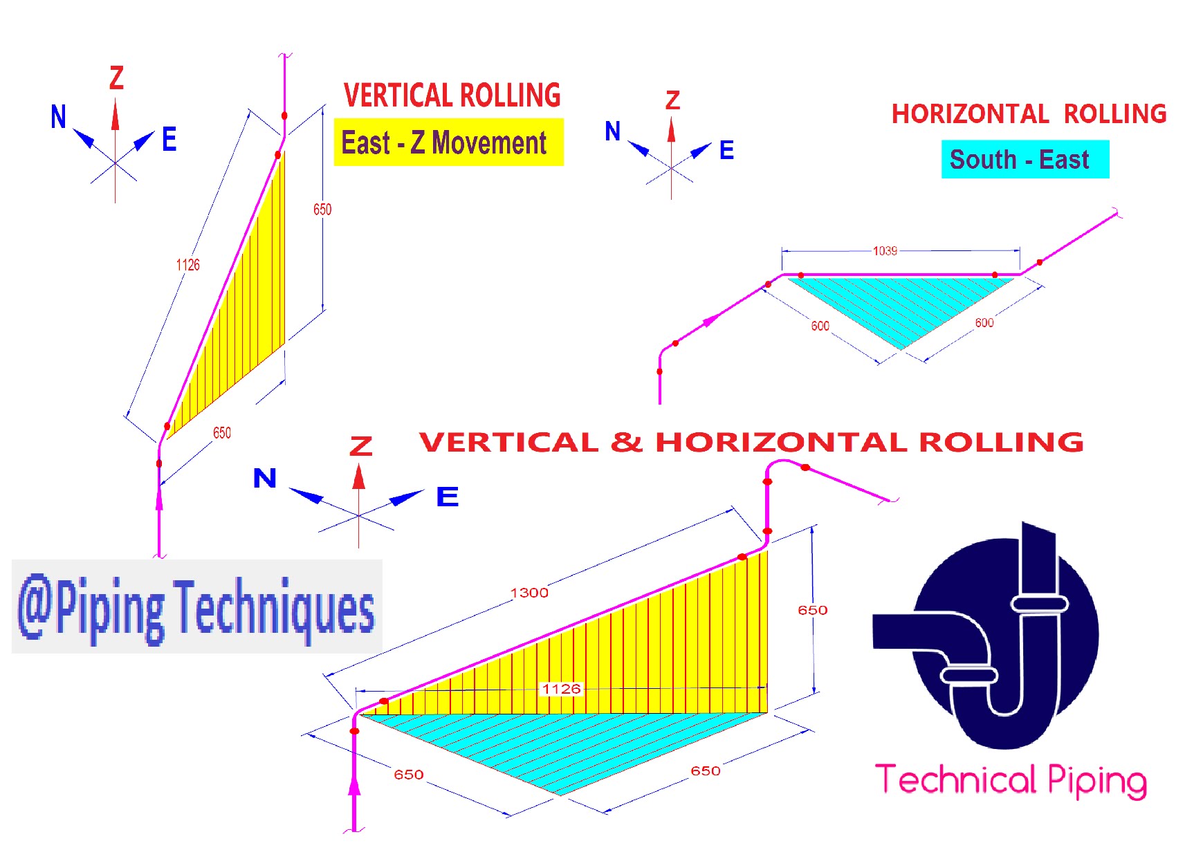
Isometric Pipe Drawing at GetDrawings Free download

How to Draw Isometric Pipe Drawings in Autocad Gautier Camonect

How to read isometric drawing piping dadver

Isometric Piping Drawings Advenser
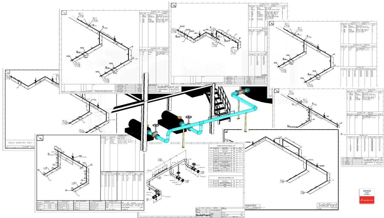
How to create piping isometric drawings with SOLIDWORKS
Piping Isometric Drawing at Explore collection of

Piping Isometric Drawing at Explore collection of

How to read piping isometric drawing, Pipe fitter training, Watch the
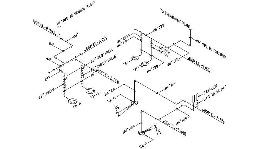
Isometric Pipe Line CAD Drawing Free Download DWG File Cadbull
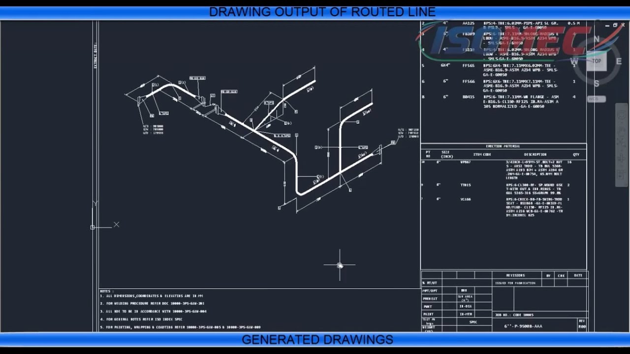
Automatic Piping Isometrics from 3D Piping Designs M4 ISO
Create Isometric Drawings In Minutes:
Web Use Basic Shapes In Isometric Drawings.
Web Iso Pipes Are Typically Drawn Using Specialized Software Such As Avicad Which Supports Isometric Drawings.
Web How To Read Piping Isometrics Using Real Plant Drawings.
Related Post: