Piping And Instrumentation Drawing
Piping And Instrumentation Drawing - Where are the inputs coming from and leading to? Web a piping & instrumentation diagram (p&id) is a schematic layout of a plant that displays the units to be used, the pipes connecting these units, and the sensors and control valves. Modern alternative to pencil and paper. A link to download this p&id is given at the end of the page. 1/5 in the series how to interpret piping and instrumentation diagrams. Standard structures located on a p&id include storage tanks, surge tanks, pumps, heat exchangers, reactors, and distillation columns. Web piping and instrumentation diagrams (p&ids) use specific symbols to show the connectivity of equipment, sensors, and valves in a control system. Web p&id drawing, or piping and instrumentation diagrams, is like a special map that shows how pipes and instruments work together in factories and plants. Web piping and instrumentation diagrams (p&ids) use specific symbols to show the connectivity of equipment, sensors, and valves in a control system. A through knowledge of the information presented in the title block, the revision block, the notes and legend, and the drawing grid is necessary before a drawing can be read. Web a piping and instrumentation diagram (p&id or pid) is a detailed diagram in the process industry which shows the piping and process equipment together with the instrumentation and control devices. Web piping & instrumentation drawings (p&ids) are important communication tools for engineers. Start doing things in edrawmax online. Identify the outputs what is the end product? In this context,. A p&id (or engineering flow drawing, efd) is a type of process engineering drawing that describes all process design aspects of a plant. It’s most commonly used in the engineering field. It's a simple way of using lines and symbols to tell the story of how liquids and gases move around, and how machines control them. Interpreting piping and instrumentation. Through a p&id, you can get the following information: P&ids provide key piping and instrumentation items along with their proper arrangement. Web piping & instrumentation drawings (p&ids) are important communication tools for engineers. Examples are piping layout, flowpaths, pumps, valves, instruments, signal modifiers, and controllers, as illustrated in figure 6. It's a simple way of using lines and symbols to. They offer a detailed overview of the process flow , including equipment, valves, and instrumentation, crucial for design and operational. In this context, process design means all the stuff that makes up a plant, including: Mechanical equipment with names and numbers. Web piping and instrumentation diagrams (p&ids) use specific symbols to show the connectivity of equipment, sensors, and valves in. Web a piping & instrumentation diagram (p&id) is a schematic layout of a plant that displays the units to be used, the pipes connecting these units, and the sensors and control valves. These symbols can represent actuators, sensors, and controllers and may be apparent in most, if not all, system diagrams. Function and purpose of p&ids. Web p&id drawing, or. Standard structures located on a p&id include storage tanks, surge tanks, pumps, heat exchangers, reactors, and distillation columns. © 2019 john wiley & sons, inc. Web p&id diagrams (piping and instrumentation diagrams) provide a schematic representation of the functional relationship between piping, instrumentation, and system components within a project. It includes all piping, instruments, valves, and equipment the system consists. Web p&id diagrams (piping and instrumentation diagrams) provide a schematic representation of the functional relationship between piping, instrumentation, and system components within a project. Web p&id drawing, or piping and instrumentation diagrams, is like a special map that shows how pipes and instruments work together in factories and plants. Standard structures located on a p&id include storage tanks, surge tanks,. P&id is more complex than pfd and includes lots of details. Web a piping and instrumentation diagram, also called p&id, is a diagram used to show a graphical display of a complete system. Web what are p&ids? Web a piping and instrumentation diagram, or p&id, shows the piping and related components of a physical process flow. Identify the inputs are. To be effective in the workplace, you must be able to read and interpret them. Web p&id drawing, or piping and instrumentation diagrams, is like a special map that shows how pipes and instruments work together in factories and plants. © 2019 john wiley & sons, inc. Web piping and instrumentation diagrams is a topic that can benefit process, project. The mechanical and electrical details of a given system or process, Web in this video, you will learn the basics of piping and instrumentation diagrams (also called p&id drawings).#pipingandinstrumentation #processcontrol #instru. To be effective in the workplace, you must be able to read and interpret them. 1/5 in the series how to interpret piping and instrumentation diagrams. It's a simple. Start doing things in edrawmax online. Web a piping and instrumentation diagram displays the piping components (for example equipment, valves, reducers and so on) of an actual physical process flow and is often used in the engineering projects, such as setting up steam boilers, heat exchangers, electric boilers and more. Web a piping and instrumentation diagram (p&id) is a comprehensive schematic that illustrates the functional relationship of piping, instrumentation, and system equipment components within a process plant. It serves as a basic document for operation, control, and shutdown schemes. Where are the inputs coming from and leading to? 1/5 in the series how to interpret piping and instrumentation diagrams. They offer a detailed overview of the process flow , including equipment, valves, and instrumentation, crucial for design and operational. Web piping and instrumentation diagrams (p&ids) use specific symbols to show the connectivity of equipment, sensors, and valves in a control system. Identify the inputs are they manual or automatic? Function and purpose of p&ids. It's a simple way of using lines and symbols to tell the story of how liquids and gases move around, and how machines control them. This information is displayed in the areas surrounding the graphic portion of the drawing. A p&id (or engineering flow drawing, efd) is a type of process engineering drawing that describes all process design aspects of a plant. Web piping & instrumentation drawings (p&ids) are important communication tools for engineers. Web piping and instrument drawings (p&ids) p&ids are usually designed to present functional information about a system or component. Web a piping and instrumentation diagram (p&id or pid) is a detailed diagram in the process industry which shows the piping and process equipment together with the instrumentation and control devices.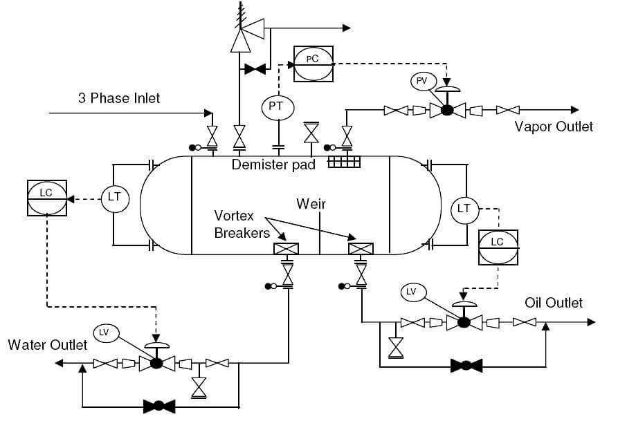
What is Piping and Instrumentation Diagram (P&ID) ? Instrumentation Tools

P & ID Diagram. How To Read P&ID Drawing Easily. Piping
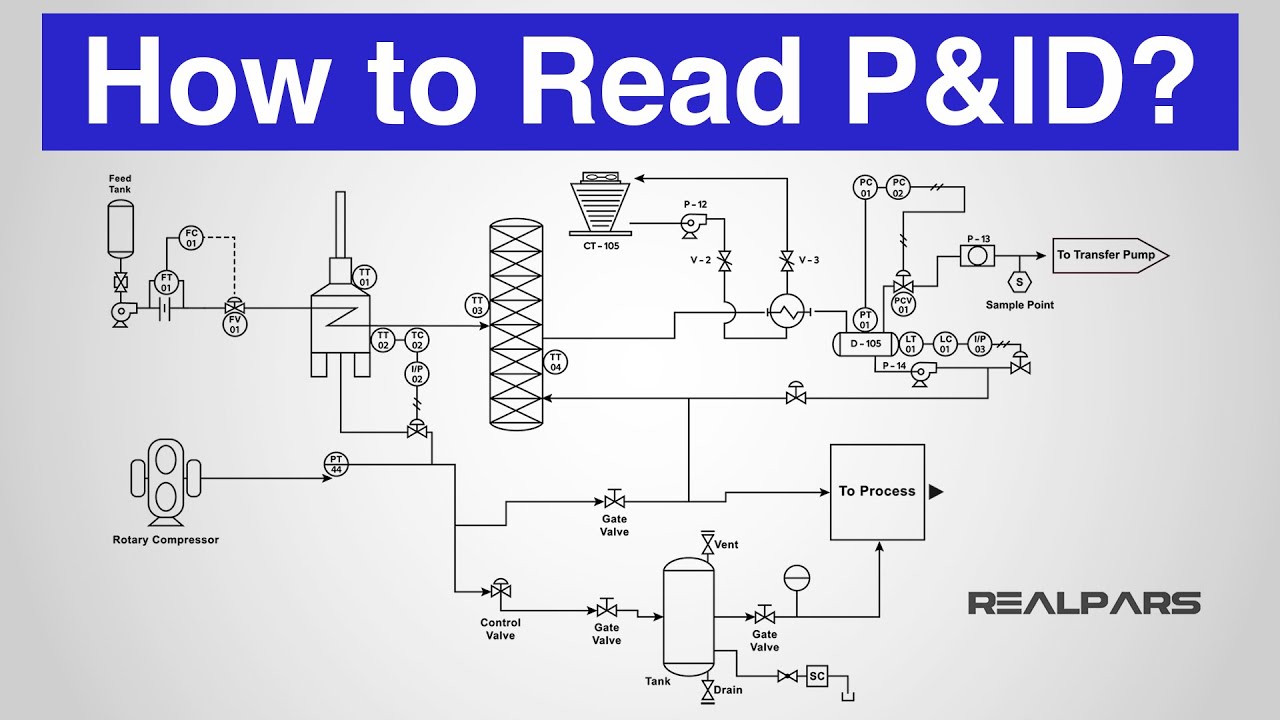
How to Read a P&ID? (Piping & Instrumentation Diagram) YouTube
![How to read a piping and instrumentation drawing? [Video] Valve Solutions](https://1.bp.blogspot.com/-GgHH1pcU0W0/WlNHvPbeyZI/AAAAAAAAAQY/NO9bREo9MDQAdPValYZ3zicXM5egYb4ygCLcBGAs/w1200-h630-p-k-no-nu/bp129.jpg)
How to read a piping and instrumentation drawing? [Video] Valve Solutions

Piping & Instrumentation Diagrams (P&IDs) Punchlist Zero
Figure A4 Piping and Instrumentation Diagram 1 Download Scientific
Piping and Instrumentation Diagram P&ID By TheEngineeringConcepts

How to Read and Interpret Piping and Instrumentation Diagrams (P&ID
Piping and Instrumentation Diagrams Tutorials III Flow and Level
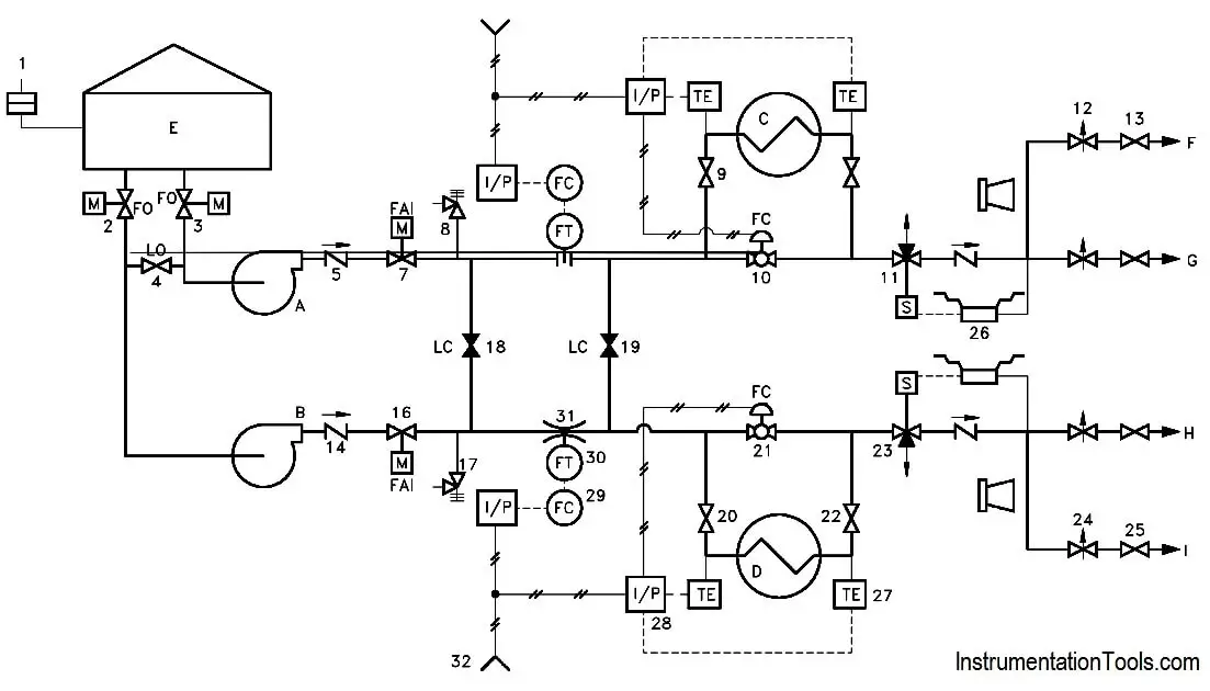
Piping and Instrumentation Documents Instrumentation Tools
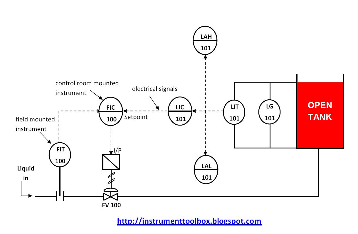
Web Piping And Instrumentation Diagrams (P&Ids) Use Specific Symbols To Show The Connectivity Of Equipment, Sensors, And Valves In A Control System.
An Essential Guide For Developing And Interpreting Piping And Instrumentation Drawings.
Web A Piping & Instrumentation Diagram (P&Id) Is A Schematic Layout Of A Plant That Displays The Units To Be Used, The Pipes Connecting These Units, And The Sensors And Control Valves.
In This Context, Process Design Means All The Stuff That Makes Up A Plant, Including:
Related Post: