Piping Drawing
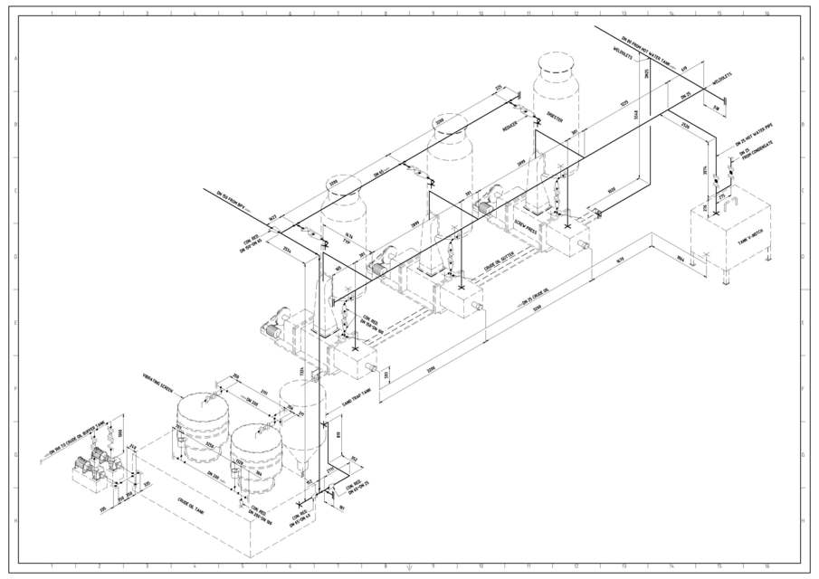
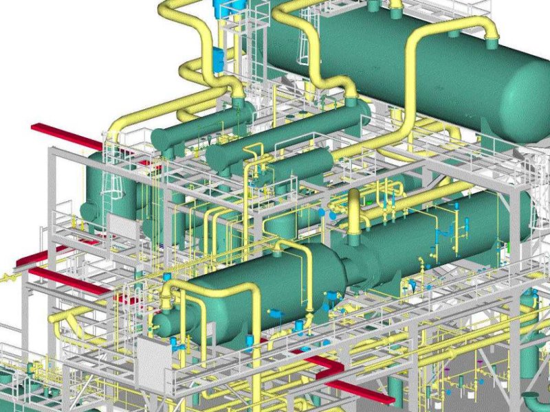
Piping Drawing - This information is displayed in the areas surrounding the graphic portion of the drawing. How to read iso drawings. We are concluding our first pipefitter series run with a video on how to draw isometric drawings. Web toolset specific objects such as autocad mep pipe objects, which are modified in autocad mep, do not appear when their drawing is attached as xref in vanilla autocad. Reading tips, symbols, and drawing techniques for engineers and piping professionals. Web easy isometric is the first pipe isometric drawing app that helps users make detailed isometric drawings in the field and without the need for tedious reference materials. They serve as a basis for studying different mechanical and chemical steps to find the root cause if something goes wrong. It’s most commonly used in the engineering field. Checkout list of such symbols given below. Examples are piping layout, flowpaths, pumps, valves, instruments, signal modifiers, and controllers, as illustrated in figure 6. Web the p&id drawings help them to track the interconnection between the piping and instrumentation and equipment. Piping isometric drawing consists of three sections. Checkout list of such symbols given below. Reading tips, symbols, and drawing techniques for engineers and piping professionals. Web in this article, we will explore all those piping drawings that are required to execute piping work. 2.8k views 3 years ago mechanical workshops. This information is displayed in the areas surrounding the graphic portion of the drawing. Web the p&id drawings help them to track the interconnection between the piping and instrumentation and equipment. Web posted in design engineering. Process flow diagram (pfd) piping and instrumentation drawing (p&id) plot. Web toolset specific objects such as autocad mep pipe objects, which are modified in autocad mep, do not appear when their drawing is attached as xref in vanilla autocad. Cad software with piping tools preinstalled. They serve as a basis for studying different mechanical and chemical steps to find the root cause if something goes wrong. Web piping isometric drawings. It’s most commonly used in the engineering field. Reading tips, symbols, and drawing techniques for engineers and piping professionals. Web piping and instrument drawings (p&ids) p&ids are usually designed to present functional information about a system or component. Web a piping isometric drawing is a technical drawing that depicts a pipe spool or a complete pipeline using an isometric representation.. A piping single line drawing (or piping one line drawing) is a piping drawing that shows the size and location of pipes, fittings and valves. When drawing piping diagrams, having the right tools is essential. 2.8k views 3 years ago mechanical workshops. The drawings would help to speed up the fabrication and erection work at the site. Start doing things. It's a simple way of using lines and symbols to tell the story of how liquids and gases move around, and how machines control them. It lists the various facility types where pipe drafting and design is applied and the types of companies that employ pipe drafters. Piping fabrication work is based on isometric drawings. 2.8k views 3 years ago. Web in this article, we will explore all those piping drawings that are required to execute piping work. Web piping and instrument drawings (p&ids) p&ids are usually designed to present functional information about a system or component. Discover the essentials of piping isometrics, including how they simplify complex piping systems for construction, maintenance, and documentation purposes. Web toolset specific objects. You can create piping drawings, which display different views of piping models. Web piping isometric drawing is an isometric representation of single pipe line in a plant. Any desired piping design views can be displayed on the drawing. General arrangement drawing (gad)/piping plan drawing. A p&id provides the design and construction sequence for the plants for systematic planning of activities. Web p&id drawing, or piping and instrumentation diagrams, is like a special map that shows how pipes and instruments work together in factories and plants. Any desired piping design views can be displayed on the drawing. Web it's quick, easy, and completely free. Web the dc public library is seeking a contractor to perform all work associated with rerouting the. The drawings would help to speed up the fabrication and erection work at the site. It is the most important deliverable of any project where piping plays a vital role. Available for windows, mac and linux. Examples are piping layout, flowpaths, pumps, valves, instruments, signal modifiers, and controllers, as illustrated in figure 6. Any desired piping design views can be. You can create piping drawings, which display different views of piping models. Piping isometric drawing consists of three sections. It is the most important deliverable of piping engineering department. This chapter is an overview of the pipe drafting and design profession. It is drawn to scale so the relationships of the aforementioned are correctly shown. These drawings are schematic representations and they would define functional relationships in a piping system. A piping single line drawing (or piping one line drawing) is a piping drawing that shows the size and location of pipes, fittings and valves. The drawings would help to speed up the fabrication and erection work at the site. It’s most commonly used in the engineering field. Pipe segments can be displayed using single line or double line representation. 2.8k views 3 years ago mechanical workshops. Web toolset specific objects such as autocad mep pipe objects, which are modified in autocad mep, do not appear when their drawing is attached as xref in vanilla autocad. Web tools you’ll need to create pipe drawings: These highly structured drawings provide a comprehensive 3d representation of the arrangement, dimensions, and connections of pipes within a system. Web it's quick, easy, and completely free. No more tedious material tracking when creating a pipe isometric drawing.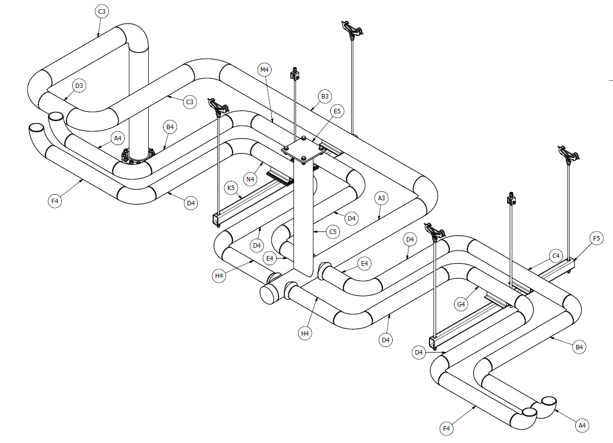
Piping Drawing at GetDrawings Free download

Piping Design Basics Piping Isometric Drawings Piping Isometrics
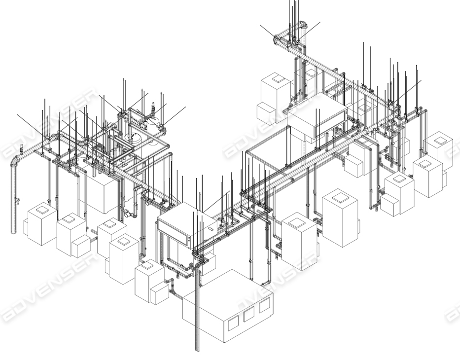
Isometric Piping Drawings Advenser
Piping Drawing at GetDrawings Free download

Piping Drawing at GetDrawings Free download
Piping Drawing at GetDrawings Free download

How to read piping Isometric drawing YouTube
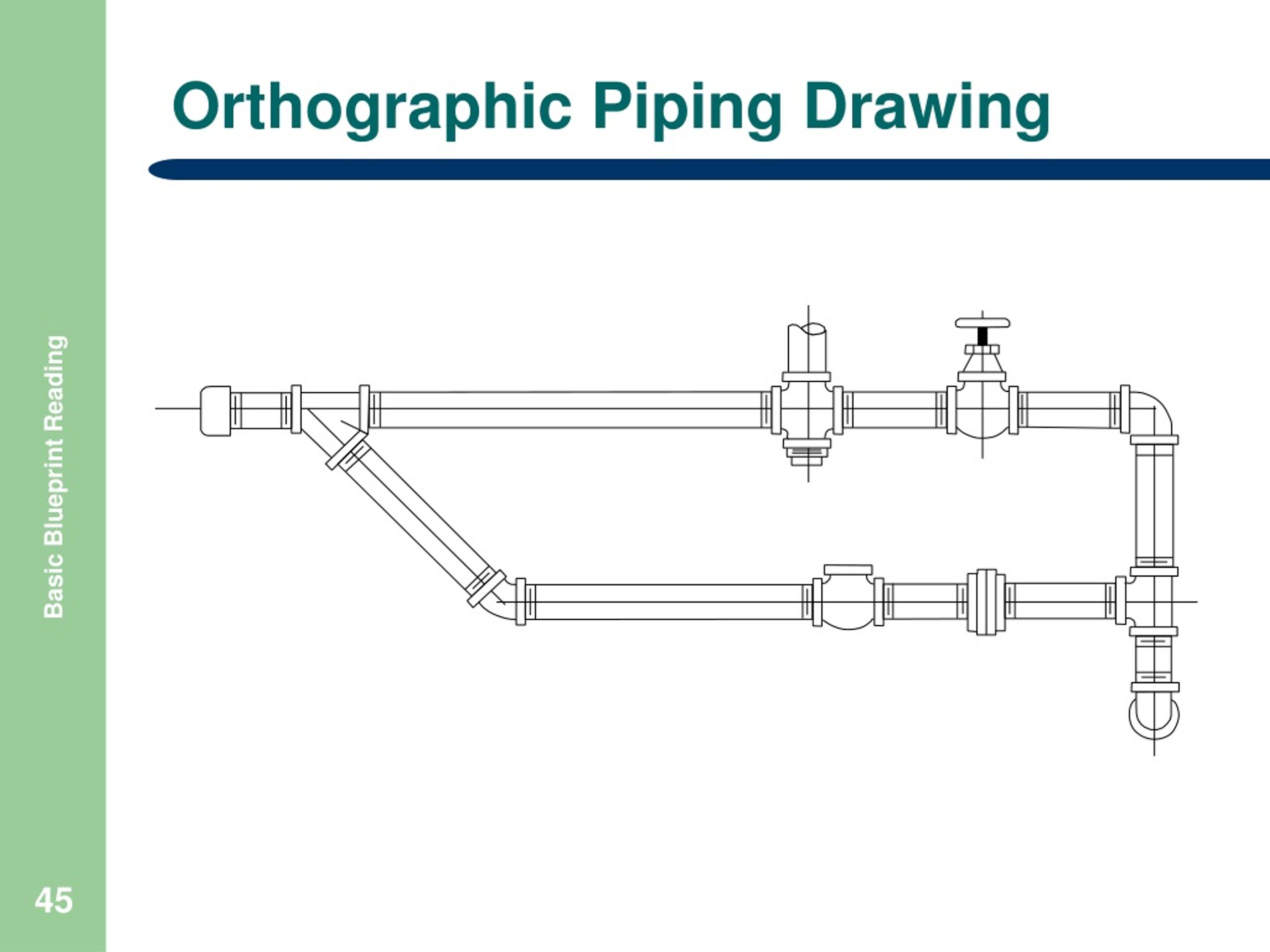
Piping orthographic drawing symbols kloology

How to read piping isometric drawing, Pipe fitter training, Watch the

Isometric Piping Drawings Advenser
Web Piping And Instrument Drawings (P&Ids) P&Ids Are Usually Designed To Present Functional Information About A System Or Component.
Any Desired Piping Design Views Can Be Displayed On The Drawing.
Cad Software With Piping Tools Preinstalled.
Web Master Piping Isometrics With Our Comprehensive Guide:
Related Post: