Piping Isometric Drawing Symbols
Piping Isometric Drawing Symbols - Web isometric drawing needs to be checked as per project standard isometric drawing checklist. Web isometric symbols for fittings, flanges, and valves represent all sizes of pipe. Web the symbols that represent fittings, valves and flanges are modified to adapt to the isometric grid. Every project has specific requirements. Various symbols are used to indicate piping components, instrumentation, equipments in engineering drawings such as piping and instrumentation diagram (p&id), isometric drawings, plot plan, equipment layout, welding drawings etc. All of our vector cad models are of the highest quality. Web the following information must be included in piping isometric drawings: Precise representation of piping components and their relationships, ensuring compatibility and functionality. Although piping isometrics are not drawn to scale, it should be drawn proportionally. Web isometric drawing symbols for piping valves. Web connections are illustrated using standard symbols. Web piping isometric drawing symbols for various markings. Isometric drawing piping symbols serve as a ready reference for the type of fittings and components. Web pipeline isometrics are detailed drawings used in engineering and design to represent the 3d layout of a pipeline system on a 2d surface. In this dwg file you. It includes general isomtric check points as well as project specific check points. Lighter lines show connected pipe, and are not parts of the symbols. Precise representation of piping components and their relationships, ensuring compatibility and functionality. The use of coordinate and elevation callouts to determine configuration dimensions of the routed pipe is explained. Web pipe drawings are much different. Web piping symbols for isometric drawings. The iso, as isometric are commonly referred, is oriented on the grid relative to the north arrow found on plan drawings. The visualization, representation, and dimensioning of single, multiangle, and rolling offsets are explained. Web isometric drawing needs to be checked as per project standard isometric drawing checklist. This information is conveyed through the. All of our vector cad models are of the highest quality. Find distributorscustom manufacturersproduct specificationsfind oems Reference number of pefs (p&id), ga drawings, line numbers, the direction of flow, and insulation tracing. Web connections are illustrated using standard symbols. Isolating, venting & draining symbols for ease of maintenance; No attempt is made to represent a pipe’s actual size or pound rating graphically. Usually, piping isometrics are drawn on preprinted paper, with lines of equilateral triangles form of 60°. The visualization, representation, and dimensioning of single, multiangle, and rolling offsets are explained. Web what is an isometric drawing? Web isometric symbols for piping fittings. Fittings, flanges, and valves play essential roles in pipeline isometric drawings, each with unique symbols according to iso standards. An isometric drawing is a type of pictorial drawing in which three sides of an object can be seen in one view. The use of coordinate and elevation callouts to determine configuration dimensions of the routed pipe is explained. Lighter lines. It includes general isomtric check points as well as project specific check points. Piping isometric dwg symbols designed just for you in autocad. In addition, an piping isometric drawing can contain further information about the components it contains by means of text annotation. Web what is an isometric drawing? Web the following information must be included in piping isometric drawings: An isometric drawing is a type of pictorial drawing in which three sides of an object can be seen in one view. Web isometric symbols for fittings, flanges, and valves represent all sizes of pipe. Web the fitting, flange, and valve drawing symbols unique to isometrics are depicted. Web piping isometric drawing symbols for various markings. Web pipeline isometrics are. Comprehensive depiction of fittings, connections, and supports, aiding in the construction and maintenance of the system. Web piping symbols for isometric drawings. No attempt is made to represent a pipe’s actual size or pound rating graphically. Web isometric symbols for fittings, flanges, and valves represent all sizes of pipe. Find distributorscustom manufacturersproduct specificationsfind oems Lighter lines show connected pipe, and are not parts of the symbols. In addition, an piping isometric drawing can contain further information about the components it contains by means of text annotation. Web pipeline isometrics are detailed drawings used in engineering and design to represent the 3d layout of a pipeline system on a 2d surface. The direction should be. It includes general isomtric check points as well as project specific check points. Reference number of pefs (p&id), ga drawings, line numbers, the direction of flow, and insulation tracing. Standards and conventions for valve status; Project specific instructions for isometrics checking. Web piping symbols for isometric drawings. Precise representation of piping components and their relationships, ensuring compatibility and functionality. Knowing the piping isometric symbols will help in recognizing the instrument and. Web pipeline isometrics are detailed drawings used in engineering and design to represent the 3d layout of a pipeline system on a 2d surface. Various symbols are used to indicate piping components, instrumentation, equipments in engineering drawings such as piping and instrumentation diagram (p&id), isometric drawings, plot plan, equipment layout, welding drawings etc. Web isometric drawing symbols for piping valves. The visualization, representation, and dimensioning of single, multiangle, and rolling offsets are explained. The use of coordinate and elevation callouts to determine configuration dimensions of the routed pipe is explained. Checkout list of such symbols given below. Although piping isometrics are not drawn to scale, it should be drawn proportionally. Web basic piping isometric symbols : The iso, as isometric are commonly referred, is oriented on the grid relative to the north arrow found on plan drawings.
Piping Isometric Drawing Symbols Pdf at Explore
Piping Coordination System Mechanical symbols for Isometric drawings

Piping Isometric DWG Symbols Free Download Drawing in CAD

Piping Isometric Drawings The Piping Engineering World
Piping Coordination System Mechanical symbols for Isometric drawings

Basic Piping Isometric Symbols Piping Analysis YouTube

How to read isometric drawing piping dadver
Piping Isometric Drawing Symbols Pdf at Explore
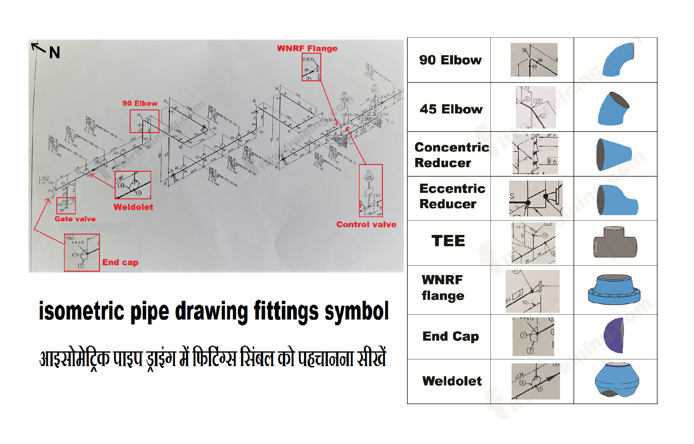
isometric pipe drawing fittings symbol Fitter training

What is Piping Isometric drawing? How to Read Piping Drawing? ALL
Lines That Indicate The Direction Of Flow, Along With Specifications About The Pipe Size, Material, And Number.
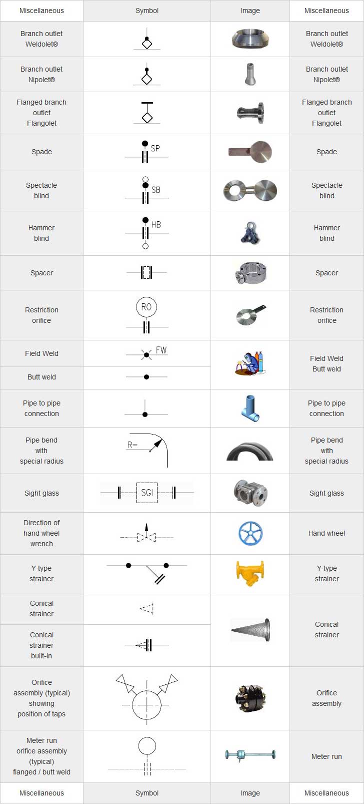
Web Piping Symbols Serve As The Alphabet Of Isometric Drawings, With Each Symbol Representing A Specific Component, Similar To Words In A Language.
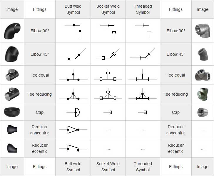
Fittings, Flanges, And Valves Play Essential Roles In Pipeline Isometric Drawings, Each With Unique Symbols According To Iso Standards.
Isometric Drawing Piping Symbols Serve As A Ready Reference For The Type Of Fittings And Components.
Related Post: