Symbol Mechanical Drawing
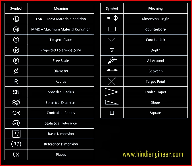
Symbol Mechanical Drawing - This document describes and illustrates common dimensioning, gd&t, architectural, piping, and electrical symbols. Aligned, the dimensions are written parallel to their dimension line. The standardization of these symbols by the iso upholds uniformity and clarity within the industry, ensuring that the symbols. In the example shown, 24 is the nominal size. The title block appears either at the top or bottom of an engineering drawing. Web symbols for indicating surface finish. Symbols or conventions used on the drawing and any additional information the designeror draftsmanfeltwas necessaryto understandthedrawing. Detailed shop drawings are created way before the beginning of the construction project and activities. Web construction drawing symbols ensure that construction documents are clear, concise and universally interpretable, facilitating global collaboration and contributing to the efficiency and success of construction projects. This list includes abbreviations common to the vocabulary of people who work with engineering drawings in the manufacture and inspection of parts and assemblies. These symbols carry specific meanings and convey vital information about various facets of a design. It is the size that the tolerance envelope is based on. Web p&id engineering drawings differ from the typical mechanical variant; Engineering drawings often contain a large amount of information, including dimensions, tolerances, annotations, and other details. Symbols or conventions used on the drawing and. Rapidograph pen and black and colored inks with graphite on cream wove paper. Classification and symbols of geometric tolerance characteristics; When standards are incorporated into a legally enforceable contract, or enacted. The standardization of these symbols by the iso upholds uniformity and clarity within the industry, ensuring that the symbols. Dimensioning and tolerancing with 45 elements; Classification and symbols of geometric tolerance characteristics; Currently, we have 16 symbols for geometric tolerances, which are categorized according to the tolerance they specify. Note the comparison with the iso standards. Pipe classes and piping line. Web the included collection of predesigned mechanical drafting symbols, machining drawing symbols, and machinist symbols helps in drawing mechanical diagrams and schematics, mechanical drafting. Web p&id engineering drawings differ from the typical mechanical variant; Web basic types of symbols used in engineering drawings are countersink, counterbore, spotface, depth, radius, and diameter. Classification and symbols of geometric tolerance characteristics; Most symbols have been in y14.5 since at least 1994. Mechanical drawing, student project, institute of design, chicago, illinois. These symbols carry specific meanings and convey vital information about various facets of a design. Read this first to find out crucial information about the drawing, including: Web these abbreviations can be found on engineering drawings such as mechanical, electrical, piping and plumbing, civil, and structural drawings. We offer you our tips which we believe are useful for dispelling uncertainty. Web engineering drawing abbreviations and symbols are used to communicate and detail the characteristics of an engineering drawing. The title block appears either at the top or bottom of an engineering drawing. However, symbols can be meaningful only if they are created according to the relevant standards or conventions. In the example shown, 24 is the nominal size. Currently, we. Note the comparison with the iso standards. Start your career in advanced manufacturing today! 4 pdh a.bhatia continuing education and development, inc. Web the included collection of predesigned mechanical drafting symbols, machining drawing symbols, and machinist symbols helps in drawing mechanical diagrams and schematics, mechanical drafting symbols chart or mechanical drawing quickly, easily, and effectively. Detailed shop drawings are created. By themselves, standards are not legally enforceable in most cases. Mechanical drawing, student project, institute of design, chicago, illinois. In the example shown, 24 is the nominal size. This document describes and illustrates common dimensioning, gd&t, architectural, piping, and electrical symbols. Engineering drawing symbols are like a secret language that only engineers can decode. It is the size that the tolerance envelope is based on. 56.2 × 43.1 cm (22 1/8 × 17 in.) credit line. Read this first to find out crucial information about the drawing, including: Engineering drawing symbols are like a secret language that only engineers can decode. Web symbols for indicating surface finish. Using abbreviations and symbols allows for concise representation, making the drawings easier to read and understand. Symbols provide a “common language” for drafters all over the world. Pipe classes and piping line. Common abbreviations include ac (alternating current), dc (direct current), fab (fabrication), and ld (load). This basic symbol consists of two legs of unequal length. This document describes and illustrates common dimensioning, gd&t, architectural, piping, and electrical symbols. Note the comparison with the iso standards. They are a highly detailed set of drawings for both installation and fabrication of the mechanical, electrical, and plumbing systems. Web engineering drawing abbreviations and symbols are used to communicate and detail the characteristics of an engineering drawing. Engineering drawing symbols are like a secret language that only engineers can decode. Rapidograph pen and black and colored inks with graphite on cream wove paper. In the example shown, 24 is the nominal size. Need to know for dispelling uncertainty in drawings. Specific piping data can be read from a diagram, including: Mechanical drawing, student project, institute of design, chicago, illinois. The table shows dimensioning symbols found on drawings. The following is a short list of symbols that normally appear on a technical drawing and need understanding. These symbols carry specific meanings and convey vital information about various facets of a design. Web may 5, 2022 by brandon fowler. You can also check out the gd&t symbols and terms on our site. Dimensioning and tolerancing with 45 elements;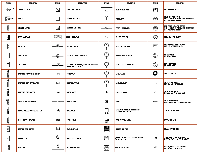
Mechanical Engineering Symbols Cadbull

Mechanical Engineering Drawing Symbols Pdf Free Download at

Mechanical Engineering Drawing Symbols Pdf Free Download at
Mechanical Engineering Drawing Symbols Pdf Free Download at

Mechanical Engineering Drawing Symbols Pdf Free Download at

Mechanical Engineering

Mechanical Drawing Symbols
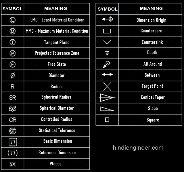
Engineering Drawing Symbols List Chart Explain Mechanical Drawing

Mechanical Drawing Symbols Mathematics Symbols Process Flow Diagram

Machine Drawing Symbols And Their Meanings Pdf mahines
This List Includes Abbreviations Common To The Vocabulary Of People Who Work With Engineering Drawings In The Manufacture And Inspection Of Parts And Assemblies.
However, Symbols Can Be Meaningful Only If They Are Created According To The Relevant Standards Or Conventions.
Unidirectional, The Dimensions Are Written Horizontally.
Ala Hijazi Engineering Working Drawings Basics Page 10 Of 22.
Related Post: